My title page contents

Capicitor Application Issues

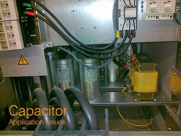
Capacitors must be built to tolerate voltages and currents in excess of their ratings according to standards. The applicable standard for power capacitors is IEEE Std 18-2002, IEEE Standard for Shunt Power Capacitors.

Heat as one of most common cause of motor failure

This slide speaks about that how motor operation fails due to heat. how heat affect motors?

Monday 26 May 2014

What will happen to the operation of Transformer if the frequency of operation is changed?

Change in frequency affects the operation of a transformer in the following ways:

i. Iron Loss – Increases with a decrease in frequency. A 60 Hz transformer will have nearly 11% higher losses, when worked on 50 Hz instead of 60 Hz. However, when a 25 Hz transformer is worked on 60Hz, iron losses are reduced by 25%.

ii. Cu Loss – In distribution transformer, it is independent of frequency.

iii. Efficiency- Since Cu loss is unaffected by change in frequency, a given transformer efficiency is less at a low frequency than at a higher one.

iv. Regulation – Regulation at unit power factor is not affected because IR drop is independent of frequency. Since reactive drop is affected, regulation at low power factor decreases with decrease in frequency and vice versa. For example, the regulation of a 25 Hz transformer when operated at 50 Hz and low power factor is much poorer.

v. Heating – Since total loss is greater at a lower frequency, the temperature is increased with decrease in frequency.

DC Machines


Discus the types and works of power plants used in ships, Airplanes, industries and commercial enterprises

Power Plants used in Industries:
 Power plants used in industries are known as captive power plants these are used only for industry demand. Type of power plant installed in industries depends upon the fuel feasibility for industry. Most of the industries use gas and diesel power plants. However nowadays industries are prone towards renewable sources of energy i.e. Solar and wind.   

Power Plants used in Airplanes:
Engine driven generators are used in airplane due to accessibility of air. Both AC and DC generators are used for electric components used in airplane. Aircraft electrical components operate  on many different voltages both AC and DC. The most of the aircraft systems use
-115 volts (V) AC at 400 hertz (Hz)
- 28 volts DC
DC power is generally provided by “self-exciting” generators containing electromagnets, where the power is generated by a commutator which regulates the output voltage of 28 volts DC. AC power, normally at a  phase voltage of 115 V, is generated by an alternator, generally in a three-phase system and at a frequency of 400Hz. For emergency purposes turbines called RAM AIR turbines are used- air driven turbine stowed in aircraft
ventral or nose section. Gen. Sizing varies between 5 and 15kVA.Rat is intended to furnish the crew with sufficient power while  attempting to restore primary generators.

Power plants used in Ships:
Power plants used on ships are generally diesel power plants. The Power Distributed on board a ship needs to be supplied efficiently throughout the ship. For this the power distribution system of the ship is used. Ship Generator consisting of prime mover and alternator .Main switch board which is a metal enclosure taking power from the diesel generator and supplying it to different machinery. Bus Bars which act as a carrier and allow transfer of load from one point to another. Circuit breakers which act as a switch and in unsafe condition can be tripped to avoid breakdown and accidents. Fuses as safety device for machinery. In case of the failure of the main power generation system on the ship, an emergency power system or a standby system is also present. The emergency power supply ensures that the essential machinery and system continues to operate the ship. Emergency power can be supplied by batteries or an emergency generator or even both systems can be used.

Power Plants used in commercial enterprises:
 Virtually all commercial electric energy is now produced by generators driven by steam from the burning of fossil fuels or from nuclear sources or by hydropower. A basic steam-power plant includes a furnace or reactor for raising the temperature of the water in a boiler, or steam generator, until it changes into steam, and a turbine, which drives the generator to produce electric power. The electric power produced is brought from the generating plant to the user through a network of wires called transmission and distribution lines.  Majority of enterprises use diesel generators to meet their requirements.


What are direct energy conversion methods for producing electric power?

: There are seven fundamental methods of directly transforming other forms of energy into electrical energy:
§  Static electricity, from the physical separation and transport of charge (examples: triboelectric effect and lightning)
§  Electromagnetic Induction, where an  electrical generator, dynamo or alternator transforms             generator kinetic energy (energy of motion) into electricity. This is the most used form for generating electricity and is based on Faraday's law. It can be experimented by simply rotating a magnet within closed loop of a conducting material (e.g. copper wire)
§  Electrochemistry, the direct transformation of chemical energy into electricity, as in a battery, fuel cell or nerve impulse.
§  Photoelectric effect, the transformation of light into electrical energy, as in solar cells
§  Thermoelectric effect, the direct conversion of temperature differences to electricity, as in thermocouples, thermopiles, and thermionic converters.
§  Piezoelectric effect, from the mechanical strain of electrically anisotropic molecules or crystals. Researchers at the US Department of Energy's Lawrence Berkeley National Laboratory (Berkeley Lab) have developed a piezoelectric generator sufficient to operate a liquid crystal display using thin films of M13 bacteriophage .
§  Nuclear transformation, the creation and acceleration of charged particles (examples: betavoltaics or alpha particle emission)

§  Ocean Wave Energy Conversion,in this method electrical energy is produced from floating thing(like ball type shape) over the waves these are connected to piston,duenwhich piston moves up and down motion and cause generator to run.

List out all energy worldwide available natural energy resources for electrical power generation.

Ans.      Energy resources are categorized in two groups conventional and non conventional. Available      resources worldwide for electrical power generation  are enlisted below:
    Conventional Sources:
  • ü  Coal Energy.
  • ü  Hydel Energy.
  • ü  Diesel Energy.
  • ü  Gas Energy.

  Non-Conventional Sources:
  • ü  Solar Energy.
  • ü  Wind Energy.
  • ü  Biomass Energy.
  • ü  Ocean Energy.
  • ü  Nuclear Energy.
  • ü  GeoThermal Energy.

Some  sources of energy are renewable like sun, wind, flowing water, ocean, wood, biomass etc. Some sources of energy are non renewable like coal, petroleum and natural gas.
Energy sources available in Pakistan are:
Thermal Energy
Thermal Energy is the oldest type of energy. With all known history available, Wood was always used for heating and cooking. In 2nd world war fossil fuels entered in the form of coal to get the energy, until liquid fuels were discovered and because of their convenience of transportation they took over as major contributors of the energy source.


1.COAL
Pakistan has huge reserves of coal which can be used to overcome the problem of energy crises in the country . The government of Pakistan is making hectic efforts to introduce the coal usage in the industrial sector. The machinery for these units is totally exempted from import duties and taxes. A coal based power plant of 150MW has been set up in the interior sindh.

1.      NATURAL OIL
Oil is one of the most important sources of energy throughout the
world and its importance is increasing day by day. many wars are
being fought just tov get the reserves of the oil..the government of
Pakistan is making sincere efforts to find out new oil fields in the
country .the policy is to attain self sufficiency in oil because oil as a
source of energy is expensive if it is imported from other countries and
it greatly increases the import bills of the country, at present the
generation capacity of electricity through oil is 12340MW

2.     Natural Gas

Natural gas   is          also a precious gift of Allah to our country. huge deposits
of natural gas has been discovered in many parts of Baluchistan and
sindh. Natural gas is a cheap sources of energy in comparison to oil
and it can also play a great role in the industrial sector because it is
used as a raw material in many industries like fertilizers cement and
plastics etc.

Hydel Energy:
In Pakistan hydel energy is usually generated through waterfalls (dams).there are many dams in the country which play a great role in the generation of electricity for household, business and industrial sector. since independence huge amounts have been allocated for the development of hydel energy as it is a main source of electricity generation in the country as a result of this the generation of electric power through hydel energy has been increased from 68MW  to 6555MW .
Nuclear Energy:
The importance of nuclear energy as a source of electricity generation is increasing very rapidly throughout the world as many developed as well as developing countries are making use of nuclear enery to generate electricity. the main fuel which is required to run the nuclear reactor is called uranium.with the grace of all mighty uranium is found in excess in Pakistan. at present there are two nuclear electric power generation plants in Pakistan namely Karachi nuclear power plant and chasma nuclear power plant.


Bio Gas
It is produced from animal and plant wastes although it is a very cheap source of energy but it can not be used on the large scale like the solar and wind energy. However it can be utilized very well in the rural areas as 72% of our population live in villages they make the best use of this source of energy .
Wind Energy:
Wind energy is a very cheap source of generating power in windy areas, the windmills can be used for supplying electricity on a small scale the windmill can be used for pumping water for crops, grinding corn, crushing sugar cane, thrashing, cutting of wood etc. at present there are four mechanical wind pumpers and one wind power generation system has been set up. Wind energy in Pakistan is in its developing stage. 500MW wind mill has been established near jhampir side (windy area  in Pakistan). Majority of Pakistanis are prone towards this type of the source in order to get electricity from an ample source available in nature.
Solar Energy:

The sun provides 170000MW of power to earth on daily basis the sunshine can also be used a cheap source of energy many developed countries as well as developing countries are now making use of the solar energy in order to fulfill their energy demand as it is a very cheap and easily available source of energy. Many steps have been  taken to boost solar energy in Pakistan by installing solar panels at various public places and institutes.
What is Turbine's Critical Frequency and why a turbine should not be operated at its critical frequency?


Turbine shaft material has its own natural frequency, when turbine rotates on such a speed that frequency of shaft become close to its natural frequency, machine causes noise & high vibrations because of resonance due to matching of frequency. Running of Steam "TURBINE" on this speed is avoided & this is called Critical speed. A turbine may have more then one critical speed, which may depend upon number of couplings.
 
A second critical speed is when the Turbine blade tips approach the speed of sound. This effectively limits the speed of a turbine and explains why power plants tend to have turbines of the same capacity.


Critical speed of the turbine is the rotor speed at which natural frequency of the assembled rotor (rotor shaft with discs, blades, shrouding strips etc in assembled condition) becomes equal to the operating speed. This is usually a expressed as a range (critical speed range).

There are multiple critical speeds. However, the operating speed of the turbine may be above or below the first / lowest critical speed. Accordingly it is called as a flexible or a rigid rotor.

Why efficiency in Thermal Power Plant is Low?

Almost 50% of the heat generated is lost at the condenser as heat rejection. It is unavoidable as with out heat rejection it is not possible to convert heat energy into mechanical energy and drive the turbine without drop in temperature. Therefore majority of the loss takes place in the condenser. Thus efficiency of the thermal power plant is between 30-35%.
On What Cycle does Thermal Power Plant operate?
Thermal Power plant works on the principle of Rankine cycle
Why Generation Voltage in Thermal Power Plant is between 11kV to 33kV?
The current carrying conductor cross section depends upon the magnitude of the current it is carrying and insulation strength of the conductor depends on the maximum voltage it can withstand. Therefore while designing the generator an optimum value is chosen between the amount of the current and voltage conductor can withstand.
What are the different circuits in Thermal Power Plant?
Some of the major circuits in the thermal power plant are:
·         Coal and Ash circuit
·         Air and gas circuit
·         Cooling water circuit
·         Feed water and steam flow circuit
How efficiency of Thermal Plant can be improved?
Some of the methods by which the efficiency of the thermal plant can be improved are:
·         By increasing the temperature and pressure of the steam entering the turbine
·         By reducing the pressure in the condenser
·         By reheating the steam between different stages between the turbine
Advantages and Disadvantages of Thermal Power Plant?
Advantages:
·         Thermal Power Plants can be operated near the load centers unlike hydro and nuclear plants
·         Requires less space compared to hydro plants and cost of construction is less
·         Running or operating costs are less compared to diesel or gas plants
·         Can able to handle over load for certain period of time
Disadvantages:
·         Emits green house gases and causes pollution
·         Coal and Ash handling requires large area
·         Efficiency is low


Electronics Fundametals Chapter 8


Saturday 24 May 2014

Discuss the criterion for choice of voltage for transmission and distribution

Criterion For Choice Of Voltage For Transmission And Distribution.

We know that the power W =VI , so for the same power if voltage is increased then current will decrease. If suppose power required is 500 W and voltage is 250 V then current I will be equal to 500/250 =2A.

Now if voltage is increased from 250V to 500V and the power required is same then I = 500/500 =1 A

Now, if the voltage is still increased to say 1000V for the same power then I = 500/1000 =0.5 A

From the above examples, we see that if the voltage is doubled, the current will be halved and when it is quadrupled then current is reduced to 1/4th of its initial value. Thus we conclude that if voltage is increased to n times then the current will be reduced to 1/nth times for the same power.With the reduction of the current to 1/nth times, the conductor area will also be reduced to 1/nth times of its original area for the same current density, Hence less material is required when the voltage is increased.

We also know that when the current passes through any conductor, there is loss of power in that particular conductor according to the relation, I2 R. As the loss is proportional to the square of the current. So if the current is reduced to ½ value , then the loss will be reduced to 1/4th its original value. Hence the efficiency of the transmission line and all others equipments associated with the line will increase and more power will be available for use.

When current is passing through a conductor there will be a voltage drop according to the relation V=IR. So, when the current is reduced the drop of the voltage is less in the line, of course with the same cross sectional area of the conductor.

With the reduction of cross sectional area, considered the main advantage of transmitting electrical energy at very high voltage viz 132kV , 220kV or even 400kV.

But in case of distribution system such high voltage is dangerous, so distribution voltage is generally 400/230V.

What are the advantages of high voltage transmission? Give its limitations also.

Ans: High voltage transmission is subdivided into HVAC and HVDC transmission systems.

(i) HVAC transmission: Advantages of HVAC transmission are as follows: As the voltage is increased, the current carried by the conductors decreases. The i2R losses correspondingly get reduced. However the cost of transmission towers, transformers, switches and circuit breakers rapidly increases with increase in voltage, in the upper ranges of a.c. transmission voltages.

(ii) HVDC transmission:
Advantages They (HVDC lines) are economical for bulk power transmission. The voltage regulation problem is much less in DC since only IR drop is involved. There is easy reversibality and controllability of power flow through a DC link. Also there is considerable insulation economy.

Limitations: The systems are costly since installation of complicated converters and DC switchgear is expensive. The converters require considerable reactive power. Lack of HVDC circuit breakers hampers network operation. Moreover there is nothing like DC transformer; voltage transformation has to be provided on the a.c. sides of the system.

Understanding Electric Utilities and De-Reguration 2ed - Lor


Electronics Fundametals Slides 7


Electronics Fundamentals Slides 6


Thursday 22 May 2014

Electronics FUndamentals Slides 5


Wednesday 21 May 2014

Electronics Fundamentals Slides 4


Electronics Fundamental slides Chapter 3


Electronics Fundamental Slides chapter 2


Tuesday 20 May 2014

Electronics Fundamentals Chapter 1


Sunday 18 May 2014

Home Made Power Plant

There is one disturbing fact that people are slowly beginning to realize. We can't depend on fossil fuels for our energy forever.
Oil prices are skyrocketing around the world. People are fighting and dying over oil reserves. The damage to our planet and our climate is irreversible and is becoming more and more apparent by the day. Put shortly, chances are that if we don't do something about our energy situation now, our kids and their kids are going to have to face some extremely difficult challenges in the future.
But what can we do? It seems that most alternative energy choices are too expensive to mass market. As an individual, is there really anything you can do to make a difference?

We're going to answer those questions and a whole lot more throughout this book. We'll look at some of things you can start doing right now, today, to do your part in solving the world's energy crisis.


Saturday 17 May 2014

Electrical Engineering MCQs


Friday 16 May 2014

Understanding Electric Power Systems


Electrical Engineering MCQs


Thursday 15 May 2014

How do the synchronizing lamps indicate the correctness of phase sequence between existing and incoming Alternators?

The correctness of the phase sequence can be checked by looking at the three sets of lamps connected across the 3-pole of the synchronizing switch. If the lamps grow bright and dark in unison it is an indication of the correctness of the phase sequence. If on the other hand, they become bright and dark one after the other, connections to any two machine terminals have to be interchanged after shutting down the machine.

State the condition to be satisfied before connecting two alternators in parallel

The following are the three conditions to be satisfied by synchronizing the additional Alternator with the existing one or the common bus-bars.

  • The terminal voltage magnitude of the incoming Alternator must be made equal to the existing Alternator or the bus-bar voltage magnitude. 
  • The phase sequence of the incoming Alternator voltage
  • The phase sequence of the incoming Alternator voltage must be similar to the bus-bar voltage. 
  • The frequency of the incoming Alternator voltage must be the same as the bus-bar voltage. 

What are the causes of changes in voltage in Alternators when loaded?

Variations in terminal voltage in Alternators on load condition are due to the following three causes:


  • Voltage variation due to the resistance of the winding, R
  • Voltage variation due to the leakage reactance of the winding, Xt
  • Voltage variation due to the armature reaction effect, Xa

How does electrical degree differ from mechanical degree?

Mechanical degree is the unit for accounting the angle between two points based on their mechanical or physical placement.

Electrical degree is used to account the angle between two points in rotating electrical machines. Since all electrical machines operate with the help of magnetic fields, the electrical degree is accounted with reference to the magnetic field. 180 electrical degree is accounted as the angle between adjacent North and South poles.

Wednesday 14 May 2014

Why are Alternators rated in kVA and not in kW?

The continuous power rating of any machine is generally defined as the power the machine or apparatus can deliver for a continuous period so that the losses incurred in the machine gives rise to a steady temperature rise not exceeding the limit prescribed by the insulation class.

Apart from the constant loss incurred in Alternators is the copper loss, occurring in the 3 –phase winding which depends on I2R, the square of the current delivered by the generator. As the current is directly related to apparent – power delivered by the generator , the Alternators have only their apparent power in VA/kVA/MVA as their power rating.

Which type of Synchronous generators are used in Hydro-electric plants and why?

As the speed of operation is low for hydro turbines use din Hydro-electric plants, salient pole type Synchronous generators are used. These allow better ventilation and also have other advantages over smooth cylindrical type rotor.

Why do cylindrical Alternators operate with steam turbines?

Steam turbines are found to operate at fairly good efficiency only at high speeds. The high speed operation of rotors tends to increase mechanical losses and so the rotors should have a smooth external surface. Hence, smooth cylindrical type rotors with less diameter and large axial length are used for Synchronous generators driven by steam turbines with either 2 or 4 poles.

Why almost all large size Synchronous machines are constructed with rotating field system type?

The following are the principal advantages of the rotating field system type
construction of Synchronous machines:
· The relatively small amount of power, about 2%, required
for field system via slip-rings and brushes.
· For the same air gap dimensions, which is normally decided
by the kVA rating, more space is available in the stator part
of the machine for providing more insulation to the system
of conductors, especially for machines rated for 11kV or
above.
· Insulation to stationary system of conductors is not
subjected to mechanical stresses due to centrifugal action.
· Stationary system of conductors can easily be braced to
prevent deformation.
· It is easy to provide cooling arrangement for a stationary
system of conductors.
· Firm stationary connection between external circuit and
system of conductors enable he machine to handle large
amount of volt-ampere as high as 500MVA.

Tuesday 13 May 2014

SF6 or Vacuum MV Circuit Breaker?


SF6 or vacuum?

Approximately 35 years ago, in the mid 1960s, two new breaker technologies, one using SF6 gas and the other vacuum as its arc quenching medium, were introduced to the market.
Research and development work on both technologies has continued unabated since then, and today it can be said that, together, they have all but replaced the older types of switchgear.
Instead of an objective selection based on real-world characteristics, the choice is very much driven by the circuit-breaker manufacturer.

There is, however, not always agreement on which criteria should be used when choosing one of these two dominant technologies.
SF6 and vacuum switchgear enjoy varying market success in the different parts of the world (Figure 1) whereas Europe and most of the Middle East countries tend to favor SF6, China, Japan and the USA definitely prefer vacuum. In other regions, the two technologies are equally popular.


Bulk-oil and minimum-oil technologies are still used in China, Eastern Europe, India and Latin America, but trends clearly indicate that these technologies will disappear very soon, to be replaced by SF6 and vacuum.
ABB concentrates today almost entirely on the two dominant technologies, and is equally present in the market with both SF6 and vacuum.
Experience with more than 300,000 MV circuit-breakers of both designs installed worldwide, backed up by over 30 years of intensive involvement in research [1], has convinced ABB that the two technologies are entirely complementary, though in some cases their different designs can be seen as alternatives.
Based on this conviction that SF6 and vacuum have equally important roles to play, the company has continued to force the development of both, and hence, as the world’s largest manufacturer of MV circuit-breakers, occupies the unique position of being able to provide unprejudiced advice and assistance in the selection of switchgear for any special application.


Capacitor Application Issues


Capacitor Ratings

Capacitors must be built to tolerate voltages and currents in excess of their ratings according to standards. The applicable standard for power capacitors is IEEE Std 18-2002, IEEE Standard for Shunt Power Capacitors.
Additional information is given in IEEE Std 1036-1992, IEEE Guide for Application of Shunt Power Capacitors. IEEE Std 18-2002 gives the following continuous overload limits.
These are “intended for contingencies and not intended to be used for a nominal design basis.
  • 110% of rated rms voltage
  • 120% of rated peak voltage
  • 135% of rated rms current (nominal current based on rated kvar and voltage)
  • 135% of rated reactive power
Short time overload voltages were specified in IEEE Std 18-1992 (on older version of the standard) and IEEE Std 1036-1992 and are listed below. These standards state that a capacitor may be expected to see a combination of 300 such overvoltages in its service life.
Note that these overvoltages are “…without superimposed transients or harmonic content”.
  • 2.20 per unit rms voltage for 0.1 seconds (6 cycles of rms fundamental frequency)
  • 2.00 per unit rms voltage for 0.25 seconds (15 cycles of rms fundamental frequency)
  • 1.70 per unit rms voltage for 1 second
  • 1.40 per unit rms voltage for 15 seconds
  • 1.30 per unit rms voltage for 1 minute
  • 1.25 per unit rms voltage for 30 minutes
An even older version of the standard, IEEE Std 18-1980, also included the following permissible overvoltages.
  • 3.00 per unit rms voltage for 0.0083 seconds (½ cycle of rms fundamental frequency)
  • 2.70 per unit rms voltage for 0.0167 seconds (1 cycle of rms fundamental frequency)
It should be noted that some capacitor manufacturers make heavy duty capacitors particularly for industrial environments.
One manufacturer makes the following claims about its heavy duty capacitors in its literature. “… they are designed to exceed the requirements of these [ANSI/IEEE, NEMA, and IEC] standards in terms of continuous rms and peak overvoltage withstand capabilities, and in tank rupture characteristics.
This manufacturer rates the continuous overvoltage capability at 125% (as opposed to 110%) and its continuous peak overvoltage capability at 135% (as opposed to 120%). When doing power system studies it is important to compare the measured or calculated voltages or currents against these ratings. In different study cases, different ratings will apply.

For example, harmonics are a steady-state phenomenon so the continuous limits would need to be considered. However, voltage harmonics resulting from a relatively short term event, such as transformer energization inrush, might be compared against the short time overload ratings.


One of the interesting implications of these overvoltage allowances is that capacitors can be applied at voltages in excess of their ratings for very short periods of time.
Why would one do this? The main reason is because the kvar produced by a capacitor is related to the square of the voltage ratio. For example, a capacitor applied at a voltage 40% higher than its nameplate will produce double its nameplate kvar.