My title page contents

Capicitor Application Issues

Capacitors must be built to tolerate voltages and currents in excess of their ratings according to standards. The applicable standard for power capacitors is IEEE Std 18-2002, IEEE Standard for Shunt Power Capacitors.

Heat as one of most common cause of motor failure

This slide speaks about that how motor operation fails due to heat. how heat affect motors?

Sunday, 10 August 2014

Typical AC Power Supply system (Generation, Transmission and Distribution) scheme and Elements of Distribution System (a complete note With Diagrams)

Typical AC Power Supply system scheme
The lines network between Generating Station (Power Station) and consumer of electric power can be divided into two parts.
  • Transmission System
  • Distribution System
We can explore these systems in more categories such as Primary transmission and secondary transmission. Similarly primary distribution and secondary distribution. This is shown in the below image (One Line or Single Line diagram of Typical AC power System Scheme)
It is not necessary that the entire steps which are sown in the above image must be included in the other power schemes. There may be difference. For example, there is no secondary transmission in many schemes, in some (small) schemes there is no transmission, but only distribution.
The following parts are shown in figure 1.
 
 
 Figure 1: single line diagram of electrical power system


  1. Generating Station
  2. Primary transmission
  3. Secondary transmission
  4. Primary Distribution
  5. Secondary Distribution
Following is detail of the above sections
 
Generating Station:
 
The place where electric power produced by parallel connected three phase alternators/generators is called Generating Station. The Ordinary generating voltage may be 11kV, 11.5 kV 12kV or 13kV. But economically, it is good to step up the produced voltage from (11kV, 11.5kV Or 12 kV) to 132kV, 220kV or 500kV or greater (in some countries, up to 1500kV) by Step up transformer (power Transformer).
 
Primary Transmission:
 
The electric supply (in 132kV, 220 kV, 500kV or greater) is transmit to load center by three phase three wire overhead transmission system.
 
Secondary transmission:
 
Area far from city (outskirts) which have connected with receiving station by line is called Secondary transmission. At receiving station, the level of voltage reduced by step-down transformers up to 132kV, 66 or 33 kV, and Electric power is transmit by three phase three wire overhead system to different sub stations. So this is a Secondary Transmission.
 
Primary Distribution:
 
At a sub station, the level of secondary transmission voltage (132kV, 66 or 33 kV) reduced to 11kV by step down transforms.
generally, electric supply is given to those  heavy consumer which demands is 11 kV, from these lines which caries 11 kV ( in three phase three wire overhead system) and they make a separate sub station to control and utilize this power.
in other cases, for heavier consumer (at large scale) their demand is about 132 kV or 33 kV.  they take electric supply from secondary transmission or primary distribution ( in 132 kV, 66kV or 33kV) and then step down the level of voltage by step-down transformers in their own sub station for utilization ( i.e. for electric traction etc).
 
Secondary Distribution:
 
Electric power is given by (from Primary distribution line i.e.11kV) to distribution sub station. This sub station is located near by consumers areas where the level of voltage reduced by step down transformers 440V by Step down transformers. These transformers called Distribution transformers, three phase four wire system). So there is 400 Volts (Three Phase Supply System) between any two phases and 230 Volts (Single Phase Supply) between a neutral and phase (live) wires. Residential load (i.e. Fans, Lights, and TV etc) may be connected between any one phase and neutral wires, while three phase load may be connected directly to the three phase lines.
 
Elements of Distribution System
 
Secondary distribution may be divided into three parts
  1. Feeders
  2. Distributors
  3. Service Lines or Service Mains 
Feeders:
 
Those Electric lines which connect Generating station (power station) or Sub Station to distributors are called feeders.
Remember that current in feeders (in each point) is constant while the level of voltage may be different; the current flowing in the feeders depends on the size of conductor.

 
Distributors:
 
Those taping which extracted for supply of electric power to the consumers or those lines, from where consumers get electric supply is called distributors.
As shown in fig 2.Current is different in each section of the distributors while voltage may be same. The selection of distributors depends on voltage drop and may be design according voltage drop. It is because consumers get the rated voltage according rules.
NOTE: the main difference between Feeder and Distributor is that Current in Feeder is same (in each section) in the other hand, Voltage is same in each section of Distributor
 
Service Lines or Service Mains:
 
The Normal cable which is connected between Distributors and Consumer load terminal called Service Line or Service Mains.
 Here is a a complete Typical AC Power Supply system scheme, in other words, the above whole story in below image.

Why the reactance of a system under fault condition is low and faults currents may raise dangerously high value. ? (With simple example)

 Because the total Power is same, and under fault condition (Short circuit)…There is no load (Impedance (Z), or Reactance ( XL)= Resistance, and in case of no load, there will be no reactance or resistance, so current will be high) in this condition…So current will be too high, and when power is same, and current increases, voltage will be decrease.
Example,
Suppose, (In normal condition)
 P= 10 watt, V = 5 Volts, and Current = 2 Amp.
But in Short circuit Condition, (When current is too high)
Then,
P = 10 Watts,    I= 10 A, so
 V = P/I….. 10 Watts/10A=1 V.
In case of short circuit, there will be no load (load = may be inductive (XL) or resistive) so when XL (We can say it resistance or opposition of current) = Zero, then Current will be too high.
So we can see that, in case of short circuit, (Faults condition) XL (inductive Reactance) =0, so Current increase, voltage decreases.

Primary and Secondary or Backup protection in a Power System

Primary Protection 
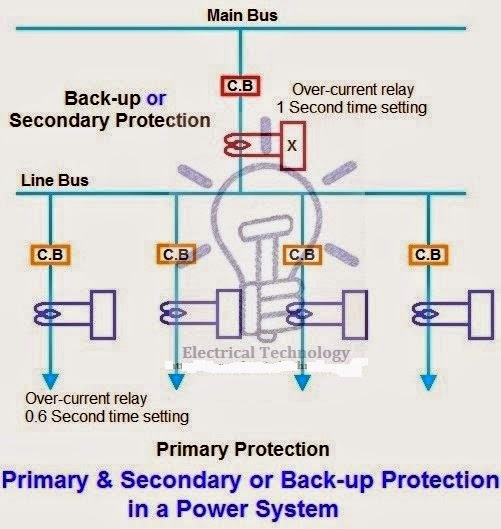
Below is the power system protection scheme which is designed to protect the power system parts and components. As shown in below fig, each line associated with over current relay that protect the lines from faults. So, if a fault happens on any line, it will be cleared by its relay and circuit breaker. This is called primary or main protection and acts as a first line defender. The service record of primary relaying is very high with well over 90% of all operations being correct. But this is not always the case, sometimes faults are not illuminated by the primary or main protection system i.e. circuit breaker and relay system because of trouble within the relays, circuit breakers or wiring system in different conditions. In those conditions, Secondary or backup protection system does the required job.


Primary protection may fail due to the following reasons
  • Failure of DC supply to the tripping Circuit
  • Failure in relay operating current or voltage
  • Failure in circuit breaker tripping mechanism
  • Failure of main protective relay operation
  • Failure in the wiring of relaying system
  • Failure of CTs or PTs operation
Secondary Protection
Back-up protection is very important for stable and reliable power system
As we know that, it is not possible to design a 100% secure and efficient system because there are possibilities of failure in the connected CTs, PTs, circuit breaker etc. in the system. If it happens, then it will destroy our whole switching system.
If the primary protection operation falls into trouble, then secondary protection disconnects the faulty part from the system. Moreover, when we disconnect primary protection for testing or maintenance purpose, then secondary or back-up protection will act as primary protection. In the above fig, relay “X” (1 Sec time setting) provides backup protection for each of the four connected lines to the main bus.
In addition, a larger part is disconnected then when primary relaying functions correctly. Therefore, greater emphasis should be placed on the better maintenance of primary relaying which is economical.

Types of Secondary or backup protection
  • Relay Backup Protection
  • Breaker Backup Protection
  • Remote Backup Protection
  • Centrally Co-ordinate Backup Protection


Sunday, 20 July 2014

Floating Neutral Impacts in Power Distribution


Introduction

If the Neutral Conductor is opened, broke or lost at either of its source side (Distribution Transformer, Generator or at Load side – Distribution Panel of Consumer), the distribution system’s neutral conductor will “float” or lose its reference ground Point. The floating neutral condition can cause voltages to float to a maximum of its Phase volts RMS relative to ground, subjecting to its unbalancing load Condition.
Floating Neutral conditions in the power network have different impact depending on the type of Supply, type of installation and Load balancing in the Distribution.
Broken Neutral or Loose Neutral would damage to the connected load or create hazardousTouch Voltage at equipment body.

  • Here We are trying to understand the Floating Neutral Condition in T-T distribution System.

What is Floating Neutral?

If the Star Point of Unbalanced Load is not joined to the Star Point of its  Power Source (Distribution Transformer or Generator) then Phase voltage do not remain same across each phase but its vary according to the Unbalanced of the load.
As the Potential of such an isolated Star Point or Neutral Point is always changing and not fixed so it’s called Floating Neutral.

Normal Power Condition and Floating Neutral Condition

Normal Power Condition:

On 3-phase systems there is a tendency for the star-point and Phases to want to ‘balance out’ based on the ratio of leakage on each Phase to Earth. The star-point will remain close to 0V depending on the distribution of the load and subsequent leakage (higher load on a phase usually means higher leakage).
Three phase systems may or may not have a neutral wire. A neutral wire allows the three phase system to use a higher voltage while still supporting lower voltage single phase appliances. In high voltage distribution situations it is common not to have a neutral wire as the loads can simply be connected between phases (phase-phase connection).

3 Phase 3 Wire System:

Three phases has properties that make it very desirable in electric power systems.
Firstly the phase currents tend to cancel one another (summing to zero in the case of a linear balanced load). This makes it possible to eliminate the neutral conductor on some lines. Secondly power transfer into a linear balanced load is constant.

3 Phase 4 Wire System for Mix Load:

Most domestic loads are single phase. Generally three phase power either does not enter domestic houses or it is split out at the main distribution board.
Kirchhoff’s Current Law states that the signed sum of the currents entering a node is zero. If the neutral point is the node, then, in a balanced system, one phase matches the other two phases, resulting in no current through neutral. Any imbalance of Load will result in a current flow on neutral, so that the sum of zero is maintained.
For instance, in a balanced system, current entering the neutral node from one Phase side is considered positive, and the current entering (actually leaving) the neutral node from the other side is considered negative.
This gets more complicated in three phase power, because now we have to consider phase angle, but the concept is exactly the same. If we are connected in Star connection with a neutral, then the neutral conductor will have zero current on it only if the three phases have the same current on each. If we do vector analysis on this, adding up sin(x)sin(x+120), andsin(x+240), we get zero.
The same thing happens when we are delta connected, without a neutral, but then the imbalance occurs out in the distribution system, beyond the service transformers, because the distribution system is generally a Star Connected.
The neutral should never be connected to a ground except at the point at the service where the neutral is initially grounded (At Distribution Transformer). This can set up the ground as a path for current to travel back to the service. Any break in the ground path would then expose a voltage potential. Grounding the neutral in a 3 phase system helps stabilize phase voltages. A non-grounded neutral is sometimes referred to as a “floating neutral” and has a few limited applications.

Floating Neutral Condition:

Power flows in and out of customers’ premises from the distribution network, entering via the Phase and leaving via the neutral. If there is a break in the neutral return path electricity may then travel by a different path. Power flow entering in one Phase returns through remaining two phases. Neutral Point is not at ground Level but it Float up to Line Voltage.
This situation can be very dangerous and customers may suffer serious electric shocks if they touch something where electricity is present.


Broken neutrals can be difficult to detect and in some instances may not be easily identified. Sometimes broken neutrals can be indicated by flickering lights or tingling taps.

  • If you have flickering lights or tingly taps in your home, you may be at risk of serious injury or even death.

Floating Neutral Impacts in Power Distribution
Floating Neutral Impacts in Power Distribution (photo by Mardix Limited; Fickr)

Introduction

If the Neutral Conductor is opened, broke or lost at either of its source side (Distribution Transformer, Generator or at Load side – Distribution Panel of Consumer), the distribution system’s neutral conductor will “float” or lose its reference ground Point. The floating neutral condition can cause voltages to float to a maximum of its Phase volts RMS relative to ground, subjecting to its unbalancing load Condition.
Floating Neutral conditions in the power network have different impact depending on the type of Supply, type of installation and Load balancing in the Distribution.
Broken Neutral or Loose Neutral would damage to the connected load or create hazardousTouch Voltage at equipment body.
Here We are trying to understand the Floating Neutral Condition in T-T distribution System.

What is Floating Neutral?

If the Star Point of Unbalanced Load is not joined to the Star Point of its  Power Source (Distribution Transformer or Generator) then Phase voltage do not remain same across each phase but its vary according to the Unbalanced of the load.
As the Potential of such an isolated Star Point or Neutral Point is always changing and not fixed so it’s called Floating Neutral.

Normal Power Condition and Floating Neutral Condition

Normal Power Condition:

On 3-phase systems there is a tendency for the star-point and Phases to want to ‘balance out’ based on the ratio of leakage on each Phase to Earth. The star-point will remain close to 0V depending on the distribution of the load and subsequent leakage (higher load on a phase usually means higher leakage).
Three phase systems may or may not have a neutral wire. A neutral wire allows the three phase system to use a higher voltage while still supporting lower voltage single phase appliances. In high voltage distribution situations it is common not to have a neutral wire as the loads can simply be connected between phases (phase-phase connection).
Healthy power system scheme

3 Phase 3 Wire System:

Three phases has properties that make it very desirable in electric power systems.
Firstly the phase currents tend to cancel one another (summing to zero in the case of a linear balanced load). This makes it possible to eliminate the neutral conductor on some lines. Secondly power transfer into a linear balanced load is constant.

3 Phase 4 Wire System for Mix Load:

Most domestic loads are single phase. Generally three phase power either does not enter domestic houses or it is split out at the main distribution board.
Kirchhoff’s Current Law states that the signed sum of the currents entering a node is zero. If the neutral point is the node, then, in a balanced system, one phase matches the other two phases, resulting in no current through neutral. Any imbalance of Load will result in a current flow on neutral, so that the sum of zero is maintained.
For instance, in a balanced system, current entering the neutral node from one Phase side is considered positive, and the current entering (actually leaving) the neutral node from the other side is considered negative.
This gets more complicated in three phase power, because now we have to consider phase angle, but the concept is exactly the same. If we are connected in Star connection with a neutral, then the neutral conductor will have zero current on it only if the three phases have the same current on each. If we do vector analysis on this, adding up sin(x)sin(x+120), andsin(x+240), we get zero.
The same thing happens when we are delta connected, without a neutral, but then the imbalance occurs out in the distribution system, beyond the service transformers, because the distribution system is generally a Star Connected.
The neutral should never be connected to a ground except at the point at the service where the neutral is initially grounded (At Distribution Transformer). This can set up the ground as a path for current to travel back to the service. Any break in the ground path would then expose a voltage potential. Grounding the neutral in a 3 phase system helps stabilize phase voltages. A non-grounded neutral is sometimes referred to as a “floating neutral” and has a few limited applications.

Floating Neutral Condition:

Power flows in and out of customers’ premises from the distribution network, entering via the Phase and leaving via the neutral. If there is a break in the neutral return path electricity may then travel by a different path. Power flow entering in one Phase returns through remaining two phases. Neutral Point is not at ground Level but it Float up to Line Voltage.
This situation can be very dangerous and customers may suffer serious electric shocks if they touch something where electricity is present.
Floating neutral condition

Broken neutrals can be difficult to detect and in some instances may not be easily identified. Sometimes broken neutrals can be indicated by flickering lights or tingling taps.
  • If you have flickering lights or tingly taps in your home, you may be at risk of serious injury or even death.

Voltage Measurement between Neutral to Ground

rule-of-thumb used by many in the industry is that Neutral to ground voltage of 2V or less at the receptacle is okay, while a few volts or more indicates overloading; 5V is seen as the upper limit.

Low Reading

If Neutral to ground voltage is low at the receptacle than system is healthy, If It is high, then you still have to determine if the problem is mainly at the branch circuit level, or mainly at the panel level.
Neutral to ground voltage exists because of the IR drop of the current traveling through the neutral back to the Neutral to ground bond. If the system is correctly wired, there should be no Neutral to Ground bond except at the source transformer (at what the NEC calls the source of the Separately Derived System, or SDS, which is usually a transformer).
Under this situation, the ground conductor should have virtually no current and therefore no IR drop on it. In effect, the ground wire is available as a long test lead back to the Neutral to ground bond.

High Reading:

A high reading could indicate a shared branch neutral, i.e., a neutral shared between more than one branch circuits. This shared neutral simply increases the opportunities for overloading as well as for one circuit to affect another.

Zero Reading:

A certain amount of Neutral to ground voltage is normal in a loaded circuit. If the reading is stable at close to 0V. There is a suspect an illegal Neutral to ground bond in the receptacle (often due to lose strands of the neutral touching some ground point) or at the subpanel.
Any Neutral to ground bonds other than those at the transformer source (and/or main panel) should be removed to prevent return currents flowing through the ground conductors.

Various Factors which cause Neutral Floating

There are several factors which are identifying as the cause of neutral floating. The impact of Floating Neutral is depend on the position where Neutral is broken:

1) At The Three Phase Distribution Transformer

Neutral failure at transformer is mostly failure of Neutral bushing.
The use of Line Tap on transformer bushing is identified as the main cause of Neutral conductor failure at transformer bushing. The Nut on Line Tap gets loose with time due to vibration and temperature difference resulting in hot connection. The conductor start melting and resulting broke off Neutral.
Poor workmanship of Installation and technical staff also one of the reasons of Neutral Failure.
A broken Neutral on Three phases Transformer will cause the voltage float up to line voltage depending upon the load balancing of the system. This type of Neutral Floating may damage the customer equipment connected to the Supply.
Under normal condition current flow from Phase to Load to Load to back to the source (Distribution Transformer). When Neutral is broken current from Red Phase will go back to Blue or Yellow phase resulting Line to Line voltage between Loads.
  • Some customer will experience Overvoltage while some will experience Low voltage.

2) Broken Overhead Neutral conductor in LV Line

The impact of broken overhead neutral conductor at LV overhead distribution will be similar to the broken at transformer. Supply voltage floating up to Line voltage instead of phase voltage. This type of fault condition may damage customer equipment connected to the supply.

3) Broken of Service Neutral Conductor

A broken Neutral of service conductor will only result of loss of supply at the customer point. No any damages to customer equipments.

4) High Earthing Resistance of Neutral at Distribution Transformer:

Good Earthing Resistance of Earth Pit of Neutral provide low resistance path for neutral current to drain in earth. High Earthing Resistance may provide high resistance Path for grounding of Neutral at Distribution Transformer.
Limit earth resistance sufficiently low to permit adequate fault current for the operation of protective devices in time and to reduce neutral shifting.

5) Over Loading and Load Unbalancing

Distribution Network Overloading combined with poor load distribution is one of the most reason of Neutral failure. Neutral should be properly designed so that minimum current will be flow in to neutral conductor. Theoretically the current flow in the Neutral is supposed to be zero because of cancellation due to 120 degree phase displacement of phase current.
  • IN= IR<0 + IY<120 + IB<-120

In Overloaded Unbalancing Network lot of current will flow in Neutral which break Neutral at its weakest point.

6) Shared neutrals

Some buildings are wired so that two or three phases share a single neutral. The original idea was to duplicate on the branch circuit level the four wire (three phases and a neutral) wiring of panel boards. Theoretically, only the unbalanced current will return on the neutral. This allows one neutral to do the work for three phases. This wiring shortcut quickly became a dead-end with the growth of single-phase non-linear loads. The problem is that zero sequence current
From nonlinear loads, primarily third harmonic, will add up arithmetically and return on the neutral. In addition to being a potential safety problem because of overheating of an undersized neutral, the extra neutral current creates a higher Neutral to ground voltage.
This Neutral to ground voltage subtracts from the Line to Neutral voltage available to the load. If you’re starting to feel that shared neutrals are one of the worst ideas that ever got translated to copper.

7) Poor workmanship and Maintenance

Normally LV network are mostly not given attention by the Maintenance Staff. Loose orinadequate tightening of Neutral conductor will effect on continuity of Neutral which may cause floating of Neutral.

How to detect Floating Neutral Condition in Panel?

Let us take one example to understand Neutral Floating Condition.We have a Transformer which Secondary is star connected, Phase to neutral = 240V and Phase to phase = 440V.

Condition (1) – Neutral is not Floating

Whether the Neutral is grounded the voltages remain the same 240V between phase & Neutral and 440V between phases. The Neutral is not Floating.

Condition (2) – Neutral is  Floating

All Appliances are connected: If the Neutral wire for a circuit becomes disconnected from the household’s main power supply panel while the Phase wire for the circuit still remains connected to the panel and the circuit has appliances plugged into the socket outlets. In that situation, if you put a voltage Tester with a neon lamp onto the Neutral wire it will glow just as if it was Live, because it is being fed with a very small current coming from the Phase supply via the plugged-in appliance(s) to the Neutral wire.
All Appliances are Disconnected: If you unplug all appliances, lights and whatever else may be connected to the circuit, the Neutral will no longer seem to be Live because there is no longer any path from it to the Phase supply.
  • Phase to Phase Voltage: The meter indicates 440V AC. (No any Effect on 3 Phase Load)
  • Phase to Neutral Voltage: The meter indicates 110V AC to 330V AC.
  • Neutral to Ground Voltage: The meter indicates 110V.
  • Phase to Ground Voltage: The meter indicates 120V.
This is because the neutral is “floats” above ground potential (110V + 120V = 230VAC). As a result the output is isolated from system ground and the full output of 230V is referenced between line and neutral with no ground connection.
If suddenly disconnect the Neutral from the transformer Neutral but kept the loading circuits as they are, Then Load side Neutral becomes Floating since the equipment that are connected between Phase to Neutral will become between Phase to Phase ( R to Y,Y to B), and since they are not of the same ratings, the artificial resulting neutral will be floating, such that the voltages present at the different equipments will no longer be 240V but somewhere between 0 (not exactly) and the 440 V (also not exactly).
Meaning that on one line Phase to Phase, some will have less than 240V and some will have higher up to near 415. All depends on the impedance of each connected item.
In an unbalance system, if the neutral is disconnected from the source, the neutral becomes floating neutral and it is shifted to a position so that it is closer to the phase with higher loads and away from the phase with smaller load. Let us assume an unbalance 3 phase system has 3 KW load in R-phase, 2 KW load in Y-phase and 1 KW load in B-phase. If the neutral of this system is disconnected from the main, the floating neutral will be closer to R-phase and away from B-phase.
So, the loads with B-phase will experience more voltage than usual, while the loads in R-phase will experience less voltage. Loads in Y-phase will experience almost same voltage. The neutral disconnect for an unbalanced system is dangerous to the loads. Because of the higher or lower voltages, the equipment is most likely to be damaged.
Here we observe that Neutral Floating condition does not impact on 3 Phase Load but It impacts  only 1 Phase Load only

How to Eliminate Neutral Floating?

There are Some Point needs to be consider to prevent of Neutral Floating.

a) Use 4 Pole Breaker / ELCB / RCBO in Distribution Panel

A floating neutral can be a serious problem. Suppose we have a breaker panel with 3 Pole Breaker for Three Phase and Bus bar for Neutral for 3 Phase inputs and a neutral (Here we have not used 4 Pole Breaker). The voltage between each Phase is 440 and the voltage between each Phase and the neutral is 230. We have single breakers feeding loads that require 230Volts. These 230Volt loads have one line fed by the breaker and a neutral.
Now suppose the Neutral gets loose or oxidized or somehow disconnected in the panel or maybe even out where the power comes from. The 440Volt loads will be unaffected however the 230V loads can be in serious trouble. With this Floating neutral condition you will discover that one of the two lines will go from 230Volts up to 340 or 350 and the other line will go down to 110 or 120 volts. Half of your 230Volt equipment will go up in high due to overvoltage and the other half will not function due to a low voltage condition. So, be careful with floating neutrals.
Simply use ELCB, RCBO or 4 Pole Circuit Breaker as income in the 3ph supply system since if neutral opens it will trip the complete supply without damaging to the system.

b) Using Voltage Stabilizer

Whenever neutral fails in three phase system, the connected loads will get connected between phases owing to floating neutral. Hence depending on load resistance across these phases, the voltage keeps varying between 230V to 400V.
A suitable servo stabilizer with wide input voltage range with high and low cutoff may help in protecting the equipments.

c) Good workmanship and Maintenance

Give higher Priority on Maintenance of  LV network  . Tight or apply adequate Torque for  tightening of Neutral conductor in LV system

Conclusion

A Floating Neutral (Disconnected Neutral) fault condition is VERY UNSAFE because If appliance is not working  and someone who does not know about the Neutral Floating could easily touch the Neutral wire to find out why appliances does not work when they are plugged into a circuit and get a bad shock. Single phase Appliances are design to work its normal Phase Voltage when they get Line Voltage Appliances may Damage.
Disconnected Neutral fault is a very unsafe condition and should be corrected at the earliest possible by troubleshooting of the exact wires to check and then connect properly.