My title page contents

Capicitor Application Issues

Capacitors must be built to tolerate voltages and currents in excess of their ratings according to standards. The applicable standard for power capacitors is IEEE Std 18-2002, IEEE Standard for Shunt Power Capacitors.

Heat as one of most common cause of motor failure

This slide speaks about that how motor operation fails due to heat. how heat affect motors?

Friday, 17 July 2015

Generator Protection

Generator Protection

GENERATOR AND ITS PROTECTION
            The core of an electrical power system is the generator. There are power units based on steam, gas, naphtha, water power, diesel engine drive and wind mills. The range of size extends from a few hundred KVA (or even less) for engine-driven and hydro sets up to turbine driven sets exceeding 500MVA in rating.
            Small and medium sized sets may be directly connected to the distribution system. A larger unit is usually associated with an individual transformer, transmission system. No switchgear is provided between the generator and transformer may be tapped off the interconnection for the supply of power to auxiliary plant. Provision of a breaker in between Generator and Transformer makes it possible to draw power for the auxiliaries through the UAT from the EHV bus, even when machine is not in service. Typical arrangements are given in figure............

Protection of  6.6 KV system in generating stations:
        Major Thermal Stations auxiliaries are fed from 6.6 KV bus which is connected by a 220/6.6KV Station Transformers and Generation voltage/6.6 KV Unit Auxiliary Transformers.

Station Transformers:
           The vector group of these transformers is Star-Delta i.e. the 6.6 KV system is delta connected Or The vector group of these transformers is Star-Star with the 6.6KV side grounded through a high resistance.
Unit Auxilary Transformers :
            The vector group of these transformers is Delta – Star (ungrounded Star on 6.6KV System).Any earth fault on the 6.6 KV system cannot be seen by any E/L relay (since the  6.6 KV system is delta connected or high resistance grounded or ungrounded Star).However 3-O/L relays are provided on the 6.6KV side of the Station Transformers and Unit Auxilary Transformers . An open-delta voltage of the 6.6 KV bus PT is connected to an over voltage relay with a very low setting.  Any earth fault on the 6.6 KV system will cause the presence of open-delta voltage and make  the voltage relay operate which is connected to give alarm.  The faulty 6.6 KV feeder can be identified by tripping the 6.6 KV outlets one after the other.

Generator Protection – Various Functions
           
            Generating units are the source of the power system and their security against any adverse conditions is most important in the system.  The generator protection must ensure a fast and selective detection of any fault in order to minimize their dangerous effects.
            Protection of passive elements like transmission lines and transformers is relatively simple which involves isolation of faulty element from the system, whereas protection of generators involves tripping of generator field breaker, generator breaker and turbine.
            Generator Protections are broadly classified into three types.

CLASS – A :- This covers all electrical protections for faults within the generating unit in which generator field breaker, generator breaker and turbine should be tripped.
CLASS – B:- This covers all mechanical protections of the turbine in which turbine will be tripped first and following this generator will trip on reverse power / low forward power protections.
CLASS – C:-   This covers electrical protection for faults in the system in which generator will be unloaded by tripping of generator breaker only.  The unit will come to house load operation and the UAT will be in service. Various protections of this class are:
 i)                   220 KV (HV side of Generator Transformer) busbar protection.
ii)                  Generator Transformer HV side breaker pole discrepancy.
iii)                Generator negative phase sequence protection
iv)                Generator Transformer over current / Earth fault protection
v)                  Reverse power protection without turbine trip.
1) Generator Differential Protection (87 G): -
It is unit type protection, covering the stator winding for phase to phase faults due to breakdown of insulation between stator phase windings.  This relay is not sensitive for single line to earth faults as the earth fault current is limited due to the high neutral earthing resistance.

If CTs of identical ratios are used on neutral and line side of generator, an operating current setting of 20% it can be adopted.  It is instantaneous in operation and it trips the generator breaker (Class – A) to eliminate the system in – feed to the fault along with field breaker and turbines.

For all machines of ratings 10 MVA and above, this protection shall be provided.
2) Generator – Transformer Differential Protection (87T):-
        This is similar to Generator Differential Protection, which covers from the generator terminals upto the HV breaker of generator transformer.  .  Sometimes this relay is not provided  where Generator and Generator Transformer Overall Differential relay (87O) is provided. 87G & 87T functions should have the features of through fault restraint, magnetising inrush restraint.

3) Generator & Generator Transformer Overall Differential Protection (87O):
         Besides generator differential and generator transformer differential, an overall differential relay can be provided between generator neutral side CTs and generator transformer Hv side CTs (and HV side CTs of UAT if provided) covering both generator and generator transformer.  The principle of operation of above relay is similar to any differential relay and it is also termed as unit differential relay.

4) Backup impedance Protection (21G):-
          This operates for phase faults in the unit, in the HV yard or in the adjacent transmission lines, with a suitable time delay.  It operates as a backup when the corresponding main protection fails.

5) Voltage restrained overcurrent protection (51 / 27 G):-
This will operate when the fault current from the generator terminals becomes low due to excitation system characteristic with under voltage criteria.
It operates as a backup protection for system faults with suitable time delay.
6) Negative phase sequence protection (46 G):-
It safeguards the generator rotor against over heating caused by the induced double frequency (100 Hz) currents when negative phase sequence currents are present in the stator.  The negative phase sequence current(I2) can appear due to unbalanced single phase loads or transmission line unsymmetrical faults 
It should be set according the Negative Phase Sequence capability of the generator 
I2**2 xt     = 30               for Thermal Units
                   = 40               for Hydro Units 
  Alarm stage can be set at 50% of continuous withstand capability of the machine with a time delay of 3 to 5 Sec.
7) Generator overloads protection (51G);-
It is used as an additional check of the stator winding temperature high protection.  The relay can be connected
               For alarm with  a setting of     110% .
                           For trip with a setting of         125%  with due time delay
8) Generator Stator Earth Fault Protection (64G):-
The high neutral earthing resistance arrangement limits the generator earth fault current, minimising the damage to core laminations.  Although a single phase earth fault is not critical, it requires clearance within a short time due to:
i)                    It may develop into a phase to phase fault
ii)                  If a second earth fault occurs the current is not longer limited by the earthing resistor.
iii)                Fire may result from earth fault arc.
a) 95% stator earth fault protection (64G1)
            It is an over voltage relay monitoring the voltage developed across the secondary of the neutral grounding transformer in case of ground faults.  It covers generator, LV winding of generator transformer and HV winding of UAT.  A pickup voltage setting of 5% is adopted with a time delay setting of about 1.0 Sec.  For all machines of ratings 10 MVA and above this shall be provided.
b) 100% stator earth fault protection (64G2);-
               This is a 3rd harmonic U/V relay.  It protects 100% of stator winding.During the machine running condition there will be certain third harmonic voltage at neutral side of the generator.This 3rd harmonic voltage will come down when a stator earth fault occurs causing this relay to operate.  This shall have voltage check or current check unit, to prevent faulty operation of the relay at generator stand still or during the machine running down period.

9)  Loss of Excitation (40G):-
 In case of loss of excitation, the generator goes out of synchronism and starts running asynchronously at a speed higher than the system, absorbing reactive power from the system.  Under these conditions, the stator end regions and part of the rotor get over heated.
 This protection shall have:
i) Mho characteristic lying in 3rd and 4th quadrants of impedance diagram with adjustable reach and offset.
ii)  An under voltage and / or overcurrent relay as additional check.
iii)  A timer with adjustable range of 1-10 Sseconds.
Recommended Settings:-
            - Diameter of Mho circle                                             =Xd
            - Off set of Mho circuit from the origin                     = xd1/2
            - Time delay                                                                = 1 Sec.
            - Under voltage relay                                                  = 110 – 115% of
 generator   rated current
10) Low Forward Power Relay (37G):-
          In thermal machines, when the steam flow through turbine is interrupted by closing the ESVs or the governor valves, the remaining steam in the turbine generates (low) power and the machine enters to motoring conditions drawing power from the system.  This protection detects low forward power conditions of the generator and trips generator breaker after a time delay, avoiding motoring of generator 
          The low forward power relay will be provided with ‘turbine trip’ interlock in thermal machines.  A setting of 0.5% of rated active power of generator with a time delay of 2.0 Sec. shall be adopted.
11) Reverse Power relay (32G):-
          Reverse power protection shall be used for all types of generators.  When the input to the turbine is interrupted the machine enters into motoring condition drawing power from the system.  Reverse power relay protects the generators from motoring condition.  In thermal machines, reverse power condition appears subsequent to low forward power condition.
         For reverse power relay, a setting of 0.5% of rated active power of generator with 2 stage timer as given below. 
i)  Stage – I: -      With turbine trip interlock, a time delay of 2 Sec. shall be adopted.
ii) Stage – II:-      Without ‘ turbine trip’  interlock, a time delay of about 20 Sec. can be adopted to avoid unnecessary tripping of unit during system disturbance causing sudden rise in frequency or power swing conditions.

12) Rotor earth fault protection: -  

           This protection shall be provided for machines of all sizes.  This protection shall be connected for alarm and the operator may take the machine at the earliest opportunity after the first earth fault has occurred.           This protection will have a sensitive voltage function operating on bridge measurement basis with auxiliary equipment. It will have two levels, one for alarm and one for trip.  The settings adopted in general are:
i)          For alarm                                 :          25 KJ Ohm, 1.0 Sec.
ii)         For trip                                    :           5 K Ohm, 0.5 Sec.


                      A modern generating unit is a complex system comprising the generator stator winding and associated transformer and unit transformer, the rotor with its field winding and exciters, and the turbine and its associated condenser and boiler complete with auxiliary fans and pumps. Faults of many kinds can occur within this system for which diverse protection applied will be governed by economic considerations, taking into account the value of the machine and its importance to the power system as a whole


13) Pole Slip Relay (98 G):
The pole slipping relay is designed to protect synchronous generators against the possibility of
the machine running unstable region of the ‘power angle curve’ which would result in power
oscillations and pole slip.  Pole slipping of generators with respect to the system leading to an
increase in rotor angular position beyond the generator transient stability limits.  Some of the
causes for pole slipping are as follows.
 i)   Large network disturbance
ii)  Faults on the network close to the generator.
iii) Loss of generator field.
iv) Operating the generator in an excessive under excited mode.
v)   Loss of evacuation.
Setting recommendations:-
a)      If the source of oscillation lies between generator/transformer unit, the machine has to be
isolated from the network after the first slip.
 Forward reach of relay characteristics shall cover generator/generator transformer. Tripping in this zone shall be in the first pole slip. The reach of this zone is =0.7x d
 b)      If the source of oscillation lies outside the unit in the network, the generator should not be
switched off until several pole slips have recurred.
14)   Generator Under Frequency Protection (81 G):
 The Under Frequency Protection:
-           Prevents the steam turbine and generator from exceeding the permissible operating time at reduced frequencies.
-           Ensures that the generating unit is separated from the network at a preset value of frequency.
-           Prevent overfluxing (v/f) of the generator (large overfluxing for short times).
            The stator under frequency relay measures the frequency of the stator terminal voltage.
Setting Recommendations:- 
For Alarm        : 48.0 Hz, 2.0 Sec. time delay. 
For Trip           : 47.5 Hz, 1.0 Sec.       (or)
                          As recommended by Generator Manufacturers.

15)     Generator Over voltage Protection (59 G):

An over voltage on the terminals of the generator can damage the insulator of the generator,
bus ducting, breakers, generator transformer and auxiliary equipment.  Hence over voltage
protection should be provided for machines of all sizes.
Settings recommendations:-
Stage-I                        : Over voltage pickup = 1.15 x Un
                                       Time delay               = 10 Sec.
State-II                        : Over voltage pickup = 1.3 x Un
                                      Time delay                = 0.5 Sec.
16) Standby Earth Fault Protection (51 NGT)
This relay monitors the current in the generator transformer neutral.  It can detect earth faults in
the Transformer HV side or in the adjacent network.
Setting recommendations:-
As this relay pickup for faults in the system, it has to be time graded with the transmission lines
emanating from that generating station. Normally IDMT relay is provided
            Operating Current Setting      = 20% In
            Operating Time                      = 1.5 to 2.0 Sec.
                                                                        (or)
                                                                Greater than  (max.) Zone-3 time of adjacent            
                                                                Transmission Lines.
            The following hazards require consideration.
a)      Stator insulation faults
b)      Overload
c)      Overvoltage
d)     Unbalanced loading
e)      Rotor faults
f)       Loss of excitation
g)      Loss of synchronism
h)      Failure of prime mover
i)        Low vacuum
j)        Lubrication oil failure
k)      Loss of boiler firing
l)        Overspeeding
m)    Rotor distortion
n)      Difference in expansion between rotating and stationary parts
o)     Excessive vibration
 Small capacity induction generators also are in service, mostly mini hydel and windmills of
capacity of 200KW to 2000KW, which depend on the system for excitation. Their protection
requirements are very simple such as overcurrent relays.
            The protective relays generally used for the synchronous generators are listed at in the
following page.
           Instead of independent relays for each function, microprocessor based numerical relay,
which can take care of the entire Generator protections the latest entry.

PROTECTIVE SCHEMES FOR VARIOUS GENERATORS

Comparision of Direct-on-line (DOL) and Star-delta Motor Starting


Motor starting methods

Direct-on-line starting (DOL)

As the name suggests, direct-on-line starting means that the motor is started by connecting it directly to the supply at rated voltage. Direct-on-line starting, (DOL), is suitable for stable supplies and mechanically stiff and well-dimensioned shaft systems – and pumps qualify as examples of such systems.
Line diagram for Direct-on-line motor starting

Where:
  • K1 – Main contactor
  • MV1 – Overload relay

Advantages of DOL

DOL starting is the simplest, cheapest and most common starting method. Furthermore it actually gives the lowest temperature rise within the motor during start up of all the starting methods.
It is the obvious choice wherever the supply authority’s current limiting restrictions allow for its use.
Power plants may have varying rules and regulations in different countries. For example:Three-phase motors with locked-rotor currents above 60 A must not use direct-on-line starting in Denmark. In such cases, it will obviously be necessary to select another starting method.
Motors that start and stop frequently often have some kind of control system, which consist of a contactor and overload protection such as a thermal relay
DOL curve – Synchronous speed / Full-load torque
.

Drawbacks of DOL

Small motors which do not start and stop frequently need only very simple starting equipment, often in the form of a hand-operated motor protection circuit breaker.
Full voltage is switched directly onto the motor terminals. For small motors, the starting torque will be 150% to 300% of the full-load value, while the starting current will be 300% to 800% of the full-load current or even higher.
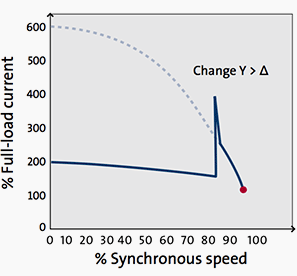
DOL curve – Synchronous speed / Full-load current

Star-delta starting

The objective of this starting method, which is used with three-phase induction motors, is to reduce the starting current.
In starting position, current supply to the stator windings is connected in star (Y) for starting. In the running position, current supply is reconnected to the windings in delta (∆) once the motor has gained speed.
Line diagram for star-delta motor starter


Advantages of Y-Δ

Normally, low-voltage motors over 3 kW will be dimensioned to run at either 400 V in delta (∆) connection or at 690 V in star (Y) connection. The flexibility provided by this design can also be used to start the motor with a lower voltage. Star-delta connections give a low starting current of only about one third of that found with direct-on-line starting.
Star-delta starters are particularly suited for high inertias, where the load are initiated after full load speed.
Start-delta starter curve – Synchronous speed / Full-load torque
 But they also reduce the starting torque to about 33%. The motor is started in Y-connection and accelerated and switched to the star-delta connection. This method can only be used with induction motors that are delta connected to the supply voltage.
  • If the changeover from star to delta takes place at too low a speed, this can cause a current surge which rises almost as high as the corresponding DOL value. During the even small period of switch over from start to delta connectionthe motor looses speed very rapidly, which also calls for higher current pulse after connection to delta. 
 The two illustrations to the right show two features which should be taken into consideration when using star-delta starting. The starter first connects the motor in star (contactor K1 and K3). After a time period – which depends on individual needs – it connects the motor indelta contactor K3 open and contactor K2 close.
Star-delta starter curve – Synchronous speed / Full-load current

Starting torque and current are considerably lower at star-delta starting than at direct-on-line starting: one third of the equivalent DOL value.
Mismatching of motor torque speed curve and load torque speed curve. In the example shown here, the motor would slowly accelerate up to approximately 50 per cent rated speed.
Mismatching of motor torque speed curve and load torque speed curve

Comparision of DOL and Star-delta starting

The following graphs illustrate currents for a Grundfos CR pump started with a Grundfos MG 7.5 kW motor by means of DOL and star-delta starting, respectively. As you will see, the DOL starting method features a very high locked-rotor current which eventually flattens and becomes constant.
Direct-on-line starting of a Grundfos 7.5 kW motor installed on a Grundfos CR pump

The star-delta starting method features a lower locked-rotor current, but peaks during the starting process as the changeover from star to delta is made.
When starting in star (t = 0.3 s), the current is reduced.
Star-delta starting of a 7.5 kW Grundfos motor installed on a Grundfos CR pump
 However, when switching over from star to delta (at t = 1 .7 s), the current pulse reaches the same level as the locked-rotor current seen with direct-on-line starting. The current pulse can even get higher, because the motor during the switching period is un-powered which means it reduce speed before the full voltage (delta voltage) are supplied.

Monday, 13 July 2015

Testing of power transformer – Measurement of impedance voltage and load loss


Purpose of the measurement

The measurement is carried out to determine the load-losses of the transformer and the impedance voltage at rated frequency and rated current.

 The measurements are made separately for each winding pair (e.g., the pairs 1-2, 1-3 and 2-3 for a three-winding transformer), and furthermore on the principal and extreme tappings.


Apparatus and measuring circuit

On Figure 1 above (Circuit for the impedance and load-loss measurement) there are following figures:
  • G1 – Supply generator
  • T1 – Step-up transformer
  • T2 – Transformer to be tested
  • T3 – Current transformers
  • T4 – Voltage transformers
  • P1 – Wattmeters
  • P2 – Ammeters (r.m.s. value)
  • P3 – Voltmeters (r.m.s. value)
  • C1 – Capacitor bank
The supply and measuring facilities are not described here. Current is generally supplied to the h.v. winding and the l.v. winding is short-circuited.

Performance of the measurement

If the reactive power supplied by the generator G1 is not sufficient when measuring large transformers, a capacitor bank C1 is used to compensate part of the inductive reactive power taken by the transformer T2.The voltage of the supply generator is raised until the current has attained the required value (25…100 % of the rated current according to the standard 4.1).

In order to increase the accuracy of readings will be taken at several current values near the required level. If a winding in the pair to be measured is equipped with an off-circuit or on-load tap-changer. the measurements are carried out on the principal and extreme tappings.

 The readings have to be taken as quickly as possible, because the windings tend to warm up due to the current and the loss values obtained in the measurement are accordingly too high.

It the transformer has more than two windings all winding pairs are measured separately.

Results

Corrections caused by the instrument transformers are made to the measured current, voltage and power values. The power value correction caused by the phase displacement is calculated as follows:
Equation 4.1 - Power value correction formula
Equation 4.1

Where:
  • Pc = corrected power
  • Pe = power read from the meters
  • δu = phase displacement of the voltage transformer in minutes
  • δi = phase displacement of the current transformer in minutes
  • Ï• = phase angle between current and voltage in the measurement (Ï• is positive at inductive load)
  • K = correction
The correction K obtained from equation 4.1 is shown as a set of curves in Figure 4.2.
The corrections caused by the instrument transformers are made separately for each phase, because different phases may have different power factors and the phase displacements of the instrument transformers are generally different.
If the measuring current Im deviates from the rated current IN, the power Pkm and the voltage Ukm at rated current are obtained by applying corrections to the values Pc and Uc relating to the measuring current.
The corrections are made as follows:
Equation 4.2 - Power Pkma
Equation 4.2

Equation 4.3 - Voltage Ukm
Equation 4.3

The correction caused by the phase displacement of instrument transformers (Figure 2):


Where:
  • K – correction in percent,
  • δu – δi – phase displacement in minutes
  • cosδ – power factor of the measurement.
The sign of K is the same as that of δu – δi.
Mean values are calculated of the values corrected to the rated current and the mean values are used in the following. According to the standards the measured value of the losses shall be corrected to a winding temperature of 75° C (80° C, if the oil circulation is forced and directed).
The transformer is at ambient temperature when the measurements are carried out. and the loss values are corrected to the reference temperature 75° C according to the standards as follows.
The d.c. losses POm at the measuring temperature Ï‘m are calculated using the resistance values R1m and R2m obtained in the resistance measurement (for windings 1 and 2 between line terminals):
Equation 4.4 - DC Losses
Equation 4.4

The additional losses Pamat the measuring temperature are:
Equation 4.5 - Additional losses
Equation 4.5

Here Pkm is the measured power, to which the corrections caused by the instrument transformer have been made, and which is corrected to the rated current according to equation (4.2).
The short-circuit impedance Zkm and resistance Rkm at the measureing temperature are:
Equation 4.6 - Short-circuit impedance
Equation 4.6

Equation 4.7 - Resistance Rkm
Equation 4.7

  • Ukm is the measured short-circuit voltage corrected according to Equation (4.3);
  • UN is the rated voltage and
  • SN is the rated power.
The short circuit reactance Xk does not depend on the losses and Xk is the same at the measuring temperature (Ï‘m) and the reference temperature (75 °C), hence:
Equation 4.8
Equation 4.8

When the losses are corrected to 75° C, it is assumed that d.c. losses vary directly with resistance and the additional losses inversely with resistance. The losses corrected to 75° C are obtained as follows:
Equation 4.9
Equation 4.9

Where:
Ï‘s = 235° C for Copper
Ï‘s = 225° C for Aluminium
Now the short circuit resistance Rkc and the short circuit impedance Zkc at the reference temperature can be determined:
Equation 4.10
Equation 4.10
 
    Equation 4.11Equation 4.11

Results

The report indicates  for each winding pair the power SN and the following values corrected to 75° C and relating to the principal and extreme tappings.
  • D.C. losses POc (PDC)
  • Additional losses Pac (PA)
  • Load losses Pkc (PK)
  • Short circuit resistance Rkc (RK)
  • Short circuit reaactance Xkc (XK)
  • Short circuit impedance Zkc (ZK)
 

2. No-Load Excitation Current

This current is measured in the winding used to excite the transformer with the other windings open-circuited. It is generally expressed in percent of the rated current of the winding. No-load excitation current is not sinusoidal and contains, as we have seen, odd harmonics (predominantly third harmonic current).

The ammeter used to record the no-load excitation current is an RMS meter which reads the square root of the sum of the squares of the harmonic currents.

Transformer Routine Test – Measurement Of No-Load Loss And Current

Introduction to test

The no-load losses are very much related to the operational performance of a transformer. As long as the transformer is operated, these losses occur. For this reason, no load losses are very important for operational economy. No-load losses are also used in the heating test.
The no-load loss and current measurements of a transformer are made while one of the windings (usually the HV winding) is kept open and the other winding is supplied at the rated voltage and frequency.

During this test the no-load current (Io) and the no-load losses (Po) are measured.

The measured losses depend heavily on the applied voltage waveform and frequency. For this reason, the waveform of the voltage should be very sinusoidal and at rated frequency.
Normally, the measurements are made while the supply voltage is increased at equal intervals from 90% to 115% of the transformer rated voltage (Un) and this way the values at the rated voltage can also be found.

No-load losses and currents

The no-load losses of a transformer are grouped in three main topics:
  1. Iron losses at the core of the transformer,
  2. Dielectric losses at the insulating material and
  3. The copper losses due to no-load current.
The last two of them are very small in value and can be ignored.
So, only the iron losses are considered in determining the no-load losses.

Measuring circuit and performing the measurement

In general according to the standards, if there is less than 3% difference between the effective (U) value and the average (U’) value of the supply voltage, the shape of the wave is considered as appropriate for measurements.

If the supply voltage is different than sinusoid, the measured no-load losses have to be corrected by a calculation. In this case, the effective (r.m.s.) value and the average (mean) value of the voltage are different. If the readings of both voltmeter are equal, there is no need for correction.

During measurements, the supply voltage U´ is supplied to the transformer by the average value voltmeter. In this way, the foreseen induction is formed and as a result of this, the hysteresis losses are measured correctly. The eddy-current losses should be corrected according to equation below.
Pm = P0 · (P1 + k · P2)
Pm: Measured loss
P0: No-load losses where the voltage is sinusoidal
Here: P0 = Ph + PE = k1 · f + k2 · f2
k = [ U / U’ ]2
P1: The hysteresis loss ratio in total losses (Ph) = k1 · f
P2: The eddy-curent loss ratio in total losses (PE) = k2 · f2
At 50 Hz and 60 Hz, in cold oriented sheet steel, P1 = P2 = % 50. So, the P0 no-load loss becomes:
Po = Pm / (P1 + k · P2)   where P1 = P2 = 0,5
According to IEC 60076-1: Pm = P0 · (1 + d)   where d = [ (U’ – U) / U’ ]

During no-load loss measurement, the effective value of the no-load current of the transformer is measured as well. In general, in three phase transformers, evaluation is made according to the average of the three phase currents.

Before the no-load measurements, the transformer might have been magnetised by direct current and it’s components (resistance measurement or impulse tests).
For this reason, the core has to be demagnetised. To do this, it has to be supplied by a voltage value (increasing and decreasing between the maximum and minimum voltage values for a few minutes) higher than the rated voltage for a certain time and then the measurements can be made.
The no-load currents are neither symmetrical nor of equal amplitude in three phase transformers. The phase angles between voltages and currents may be different for each of three phases.
For this reason, the wattmeter readings on each of the three phases may not be equal. Sometimes one of the wattmeter values can be 0 (zero) or negative (-).