


Capicitor Application Issues
Capacitors must be built to tolerate voltages and currents in excess of their ratings according to standards. The applicable standard for power capacitors is IEEE Std 18-2002, IEEE Standard for Shunt Power Capacitors.

Heat as one of most common cause of motor failure
This slide speaks about that how motor operation fails due to heat. how heat affect motors?
Saturday, 2 July 2016
Monday, 27 June 2016
Introduction of Grid Station Main and Auxiliary Equipment
7-1 TRANSFORMERS
Electrical transformer is a static device which transforms electrical energy from one circuit to another without any direct electrical connection and with the help of mutual induction between to windings. It transforms power from one circuit to another without changing its frequency but may be in different voltage level.
7-1-1 USE OF POWER TRANSFORMER
Generation of Electrical Power in low voltage level is very much cost effective. Hence Electrical Power is generated in low voltage level. Theoretically, this low voltage leveled power can be transmitted to the receiving end. But if the voltage level of a power is increased, the current of the power is reduced which causes reduction in ohmic or I2R losses in the system, reduction in cross sectional area of the conductor i.e. reduction in capital cost of the system and it also improves the voltage regulation of the system. Because of these, low leveled power must be stepped up for efficient. This is done by step up transformer at the sending side of the power system network. As this high voltage power may not be distributed to the consumers directly, this must be stepped down to the desired level at the receiving end with help of step down transformer. These are the use of electrical power transformer in the electrical power system.
7-1-2 TYPES OF TRANSFORMER
Transformers can be categorized in different ways, depending upon their purpose, use, construction etc. The types of transformer are as follows:
Step Up Transformer & Step Down Transformer - Generally used for stepping up and down the voltage level of power in transmission and distribution power network.
Three phase transformer & Single Phase Transformer - Former is generally used in three phase power system as it is cost effective than later but when size matters it is preferable to use three phase transformer as it is easier to transport three single phase unit separately than one single three phase unit.
Electrical Power Transformer, Distribution Transformer & Instrument Transformer - Transformer generally used in transmission network is normally known as Power Transformer, Distribution Transformer is used in distribution network and this is lower rating transformer and Current Transformer & Potential Transformer, we use for relay and protection purpose in electrical power system and in different instruments in industries are called instrument transformer.
Two Winding Transformer & Auto-Transformer - Former is generally used where ratio between High Voltage and Low Voltage is greater than 2. It is cost effective to use later where the ratio between High Voltage and Low Voltage is less than 2.
Outdoor Transformer & Indoor Transformer - Transformers designed for installing at outdoor is Outdoor Transformer and Transformers designed for installing at indoor is Indoor Transformer.
7-2 CIRCUIT BREAKERS
Circuit Breaker is a switching device which can be operated manually as well as automatically for controlling and protection of electrical power system respectively. As the modern power system deals with huge currents, special attention should be given during designing of circuit breaker to safe interruption of arc produced during the operation of circuit breaker
The modern power system deals with huge power network and huge numbers of associated electrical equipment. During short circuit fault or any other types of electrical fault these equipment as well as the power network suffer a high stress of fault current in them which may damage the equipment and networks permanently. For saving these equipments and the power networks the fault current should be cleared from the system as quickly as possible. Again after the fault is cleared, the system must come to its normal working condition as soon as possible for supplying reliable quality power to the receiving ends. In addition to that for proper controlling of power system, different switching operations are required to be performed. So for timely disconnecting and reconnecting different parts of power system network for protection and control, there must be some special type of switching devices which can be operated safely under huge current carrying condition. During interruption of huge current, there would be large arcing in between switching contacts, so care should be taken to quench these arcs in safe manner.
Circuit breaker is the special device which does all the required switching operations during current carrying condition.
7.2.1 WORKING PRINCIPLE OF CIRCUIT BREAKER
Circuit breaker mainly consists of fixed contacts and moving contacts. In normal "ON" condition of circuit breaker, these two contacts are physically connected to each other due to applied mechanical pressure on the moving contacts. There is an arrangement stored potential energy in the operating mechanism of circuit breaker which is realized if switching signal given to the breaker. The potential energy can be stored in the circuit breaker by different ways like by deforming metal spring, by compressed air, or by hydraulic pressure. But whatever the source of potential energy, it must be released during operation. Release of potential energy makes sliding of the moving contact at extremely fast manner.
All circuit breaker have operating coils (tripping coils and close coil), whenever these coils are energized by switching pulse, and the plunger inside them displaced. This operating coil plunger is typically attached to the operating mechanism of circuit breaker, as a result the mechanically stored potential energy in the breaker mechanism is released in forms of kinetic energy, which makes the moving contact to move as these moving contacts mechanically attached through a gear lever arrangement with the operating mechanism. After a cycle of operation of circuit breaker the total stored energy is released and hence the potential energy again stored in the operating mechanism of circuit breaker by means of spring charging motor or air compressor or by any other means.
Till now we have discussed about mechanical working principle of circuit breaker. But there are electrical characteristics of a circuit breaker which also should be considered in this discussion of operation of circuit breaker.
The circuit breaker has to carry large rated or fault power. Due to this large power there is always dangerously high arcing between moving contacts and fixed contact during operation of circuit breaker.
Again as we discussed earlier the arc in circuit breaker can be quenched safely if the dielectric strength between the current carrying contacts of circuit breaker increases rapidly during every current zero crossing of the alternating current. The dielectric strength of the media in between contacts can be increased in numbers of ways, like by compressing the ionized arcing media since compressing accelerates the deionization process of the media, by cooling the arcing media since cooling increase the resistance of arcing path or by replacing the ionized arcing media by fresh gasses. Hence a numbers of arc quenching processes should be involved in operation of circuit breaker.
7.2.2 TYPES OF CIRCUIT BREAKER
According to different criteria there are different types of circuit breaker
Classification Based on Arc Quenching Media:
1. Oil Circuit Breaker
2. Air Circuit Breaker
3. SF6 Circuit Breaker
4. Vacuum Circuit Breaker
Classification Based on Service:
1. Outdoor Circuit Breaker
2. Indoor Circuit Breaker
Classification Based on Operating Mechanism of circuit breaker:
1. Spring Operated Circuit Breaker
2. Pneumatic Circuit Breaker
3. Hydraulic Circuit Breaker
Classification Based on Voltage level of installation:
1. High Voltage Circuit Breaker
2. Medium Voltage Circuit Breaker
3. Low Voltage Circuit Breaker
7.3 DISCONNECT SWITCHES/ISOLATORS
In electrical engineering, a disconnector or isolator switch or disconnect switch is used to make sure that an electrical circuit can be completely de-energized for service or maintenance. Such switches are often found in electrical distribution and industrial applications where machinery must have its source of driving power removed for adjustment or repair. High-voltage isolation switches are used in electrical substations to allow isolation of apparatus such as circuit breakers and transformers, and transmission lines, for maintenance. Often the isolation switch is not intended for normal control of the circuit and is used only for isolation.
Isolator switches have provisions for a Padlock so that inadvertent operation is not possible. In high voltage or complex systems, these padlocks may be part of a trapped-key interlocked to ensure proper sequence of operation. In some designs the isolator switch has the additional ability to earth the isolated circuit thereby providing additional safety. Such an arrangement would apply to circuits which inter-connect power systems where both end of the circuit need to be isolated.
The major difference between an isolator and a circuit breaker is that an isolator is an off-load device intended to be opened only after current has been interrupted by some other control device. Safety regulations of the utility must prevent any attempt to open the disconnector while it supplies a circuit.
7-4 LIGHTNING ARRESTER
A lightning arrester (in Europe: surge arrester) is a device used on electrical power system and communications systems to protect the insulation and conductors of the system from the damaging effects lightning. The typical lightning arrester has a high voltage terminal and a ground terminal. When a lightning surge (or switching surge, which is very similar) travels along the power line to the arrester, the current from the surge is diverted through the arrestor, in most cases to earth.
If protection fails or is absent, lightning that strikes the electrical system introduces thousands of kilovolts that may damage the transmission lines, and can also cause severe damage to transformers and other electrical or electronic devices. Lightning-produced extreme voltage spikes in incoming power lines can damage electrical home appliances.
A lightning arrester may be a spark gap or may have a block of a semiconducting material such as Silicon Carbide or Zinc Oxide. Some spark gaps are open to the air, but most modern varieties are filled with a precision gas mixture, and have a small amount of radioactive material to encourage the gas to ionize when the voltage across the gap reaches a specified level. Other designs of lightning arresters use a glow-discharge tube (essentially like a neon glow lamp) connected between the protected conductor and ground, or voltage-activated solid-state switches called varistors or MOVs.
Lightning arresters built for power system consist of a porcelain tube several feet long and several inches in diameter, typically filled with disks of zinc oxide. A safety port on the side of the device vents the occasional internal explosion without shattering the porcelain cylinder.
Lightning arresters are rated by the peak current they can withstand the amount of energy they can absorb, and the break over voltage that they require to begin conduction. They are applied as part of a lightning protection system, in combination with air terminals and bonding.
7-5 BATTERIES AND BATTERY CHARGERS
Supply of power to protection and control circuits is provided from storage batteries due to reliability point of view.
The simplest operating unit to produce emf chemically is called a cell, whereas several cells constitute a battery. Electrochemical devices consist of two dissimilar electrodes immersed in a conducting solution, normally known as electrolyte that is capable of storing electrical energy.
The voltage of the cell depends upon the material of electrolyte, while the current and power capacity of a cell depends upon the plate area and weight of active material in the electrodes.
Main types of storage batteries are:
Lead Acid Batteries
Alkaline Batteries
Active Parts of Lead Acid Battery:
Grid (Lead Antimony)
Positive Plates (Lead Per Oxide- PbO2)
Negative Plates (Lead- Pb)
Electrolyte (Sulphuric Acid-H2SO4)
Chemical Reactions
At Anode: PbO2 + H2SO4↔ PbSO4 + H2O + ½O2
At Cathode: Pb + H2SO4↔ PbSO4 + H2O
7-6 STATION GROUNDING SYSTEM
Earthing or grounding is the term used for electrical connection to general mass of earth in such a manner as to ensure, at all times, an immediate discharge of energy without danger. A grounding system to be totally effective must satisfy the following conditions:
Provide a low impedance path to ground for personnel and equipment protection and effective circuit relaying.
Withstand and dissipate repeated fault and surge currents.
Provide corrosion allowance or corrosion resistance to various soil chemicals to insure continuous performance during the life of the equipment being protected.
Types of Earthing:
Solid or Effective Earthing
Resistance Earthing/Reactance Earthing
Classification of Earthing
System or Neutral Earthing: The neutral point of generator, transformer, transmission and distribution system or circuit, rotating machines etc. is connected to earth either directly or through a resistance, or a reactance.
Equipment Earthing: Equipment Earthing means connecting the non current carrying metallic parts in the neighborhood of electrical circuits to earth.
Resistance to current through an earth electrode system has the following three components:
Resistance of the ground rod itself and connections to it.
Contact resistance between the ground rod and earth adjacent to it.
Resistance of the surrounding earth.
7-7 AC & DC Supply System
In any substation AC and DC supply system plays a very important role for protection, control and for all auxiliary services.
AC Supply System
For AC supply, normally a dedicated panel is specified in a substation which is only for the substation and no external load is connected to it in order to avoid interruptions on it. On the LT side two transformers are provided exclusively for the substation auxiliary services. For reliability purposes, load is fed from one transformer; however in case load can be shifted to the other transformer either from HT or LT side. Then we have distribution panels, from where load is distributed throughout the substation through appropriate Circuit Breakers/ Miniature Circuit Breakers.
DC Supply System
For DC supply system, Rectifiers, Batteries and Distribution Panels are provided in the substation. In important substations, normally Two sets of Batteries along with Three Rectifiers (One as standby) are provided for reliability purposes.
110 Volts Batteries Two Sets
110 Volts Rectifiers Three Sets
220 Volts Batteries Two Sets
220 Volts Rectifiers Three Sets
In 500 kV substations, Four sets of Batteries and Six Rectifiers (One as standby for Two banks). Even, in case of emergency, loads of the same rating can be coupled with one Rectifier/Battery.
7.8 POWER CABLES
There are four main parts of cable:-
1. Conductor
2. Insulation
3. Shield or Sheath
4. Protective Covering
7.8.1 PURPOSES OF SHIELDING / SHIELD GROUNDING
The application of conducting (copper etc) and semiconducting (metabolized paper tap or containing carbon or silicon etc) materials over the conductor insulation is called shielding. The main purpose of shield is to keep even voltage gradient across the insulation in order to avoid damage to insulation by corona or ionization.
Now shield may have induced voltages in it, so shield must be grounded in order to discharge these induced voltages. When shield is grounded, it provides some more advantages as well, which are:
1. Provides earth return path in case of phase to ground fault
2. Human safety
3. Protects the cable from external high voltages, produced by lightening etc
Shield must be grounded at one place only (especially in single phase cable) in order to avoid flow of current in shield and hence damage to it due to overheating. Shielding idea was given by Martin Hochsadter in 1915. He gave the idea that put shield around the conductor of each phase and then ground all shields. Such cables are called H-cables. Such cable fails phase to ground. In these cables it is very rare that cable may fail phase to phase.
In a very long cable, sectionalized are used. In sectionalized shield each section is insulated from each other and then each section is grounded at one place only.
7.9 BUS-BARS
There are two types of bus bars used in grid station, which are:
1. The Flexile or Stranded Bus Bar
2. The Rigid Bus Bar (may be tubular or solid)
1. Flexible or Stranded Bus Bar: It is used where:
A. Longer spans are involved.
B. Where sufficient clearances are needed to allow for conductor sways and.
C. It is used as a long drop from horizontal bus to equipment bushing.
In the flexible bus bar sag must be enough to account for temperature variations without affecting the clearances between phases and phases to ground.
2. Rigid Bus Bar: It is used where:
A. Heavy currents are involved
B. Short or less Spacing is available
To account for thermal expansion /contraction of rigid bus provision must be made by means of expansion joints and clamps to permit bus to slide both ways in order to avoid damage to equipment bushing and isolators etc.

Thursday, 14 January 2016
7 guide lines to correctly select circuit breaker
7 guide lines to correctly select circuit breaker
Selection of rated circuit breaker //
The general procedure for the selection of correctly rated circuit breaker follows the following scheme of seven major questions you should answer:
1. What is the task of the branch circuit or feeder?
Will it be used for the protection of connecting leads, protection of installation, group-protection or motor protection? Select the appropriate circuit breaker type, with or without the thermal overload protection. Decide which type of protective characteristic (cable or motor protection).
2. Which rated current / setting range?
Do the setting ranges of the thermal and the magnetic release cover the requirements of the particular application (protection of transformer or generator)?
The setting ranges of the various sizes of circuit breakers are overlapping. The same current settings may be partly covered by more than one size of circuit breakers (as for example 80 A setting can be covered by two or more CB sizes, 100A or 125A).
The following features depend on the size of the circuit breakers:
Accessories (as for example types and numbers of auxiliary contacts),Mode of operation (toggle or rotating handle),Mode of mounting (snap-on or screw mounting) orThe electrical characteristics (breaking capacity, selectivity etc.).
3. Breaking / making capacities / rated operational voltage?
Where is the point of installation of the circuit breaker?What is the expected agnitude of the prospective short-circuit current at that location?Is a lower making/breaking capacity acceptable (appreciable reduction of the short-circuit current due to long connecting leads or due to other short circuit protective devices connected upstream)?Is the breaking capacity reduced due to higher rated operational voltage (as for example >400 V)?Does it indicate a selection on the basis of Icu (rated ultimate short-circuit breaking capacity, reduced functional capability after the interruption of a short-circuit) or on the basis of Ics (rated service short-circuit breaking capacity, full functional capability after the interruption of the short-circuit)?With the help of an efficient group-protection, can smaller and less expensive circuit breakers be utilised?
Not sure what are the breaking and making capacity?
4. Any special requirements?
Must reduction factors for the rated current be taken into account due to: ambient air temperature (>40…60 °), altitude of the site of installation (>2000 m above m.s.l), higher supply frequency (>400 Hz)?
5. Which type of co-ordination?
Selection of the downstream contactor in accordance with the type of co-ordination type “1” or type “2”?
6. What is the mode of mounting?
Deciding factor for the supporting/adapter plates of the modular mounting system (suitability for the selected type of circuit breaker).
7. Cross-section of the connecting wire/cable?
The cross-section of the connecting leads to the motors are to be selected on the basis of the current setting of the thermal overload release of the circuit breaker. Eventually, the maximum permissible length of the connection is to be considered (shock hazard due to touch potential in the case of a short-circuit).
Capacitive Voltage Transformers for HV Measurements
Transformers (CVT) For HV Measurements
66 kV and upwards //
Capacitive voltage transformers (CVTs) are used on higher voltage levels, starting from 66 kV and upwards. The type of the CVT is always a single-pole one, thus the connection is between phase and earth. The higher the voltage level is, the more price-competitive the capacitive type becomes.
One of the advantages the capacitive type has, in comparison to the inductive type, is the possibility to use capacitive voltage transformers as high-frequency coupling unitstowards the primary system (over headlines).
A typical application would be to utilize the CVTs for power line carrier (PLC)high-frequency signal interface units. For the voltage measurement purposes, the behavior and the data specification of CVTs follow the same guide lines as the inductive ones.
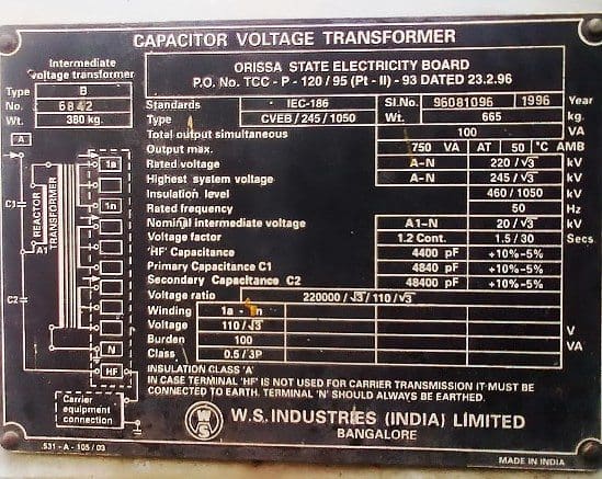
In addition, the possibility for high-frequency signal coupling calls for a specified value for rated capacitance (Cn).
This value is chosen considering the following issues //
Voltage magnitude to be measuredDemands from PLC system (frequency, bandwidth, connections)Capacitive voltage transformer manufacturing considerations
The construction of capacitive voltage transformers
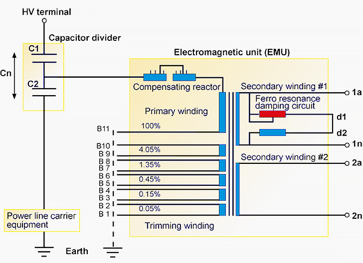
The figure above shows the principle of a capacitive voltage divider on which the capacitive voltage transformer is based. The trimming windings are used for fine tuning the output signal to correspond with the required accuracy class requirements. The compensating reactor compensates the phase angle shift caused by the capacitive voltage divider.
All capacitive voltage transformers require some sort of ferroresonance damping circuit.
The capacitance in the voltage divider, in series with the inductance of the compensating reactor and the wound transformer (inside the electromagnetic unit EMU), constitutes a tuned resonance circuit. Unlike with the inductive type of voltage transformers the CVTs usually have the ferroresonance damping circuit inbuilt in the CVT itself, as shown in the previous figure.
At higher system voltages, the resonance phenomenon usually takes place on fundamental or on sub-harmonic frequencies, resulting in voltage transformer heating (finally damages) and non-selective operations of protective relaying possible protective relaying non-selective operations.
The modern CVTs are utilizing the so-called “adaptive” damping circuits.
The circuit consists of a saturable series reactor and a loading resistor. This circuit is connected in parallel to one of the secondary cores. During ferroresonance conditions, high voltages appear, saturating the reactor and turning the damping resistor on to effectively mitigate the parasitic voltage. During normal system conditions, the reactor presents high reactance, effectively “switching off” the damping resistor.
Possible triggering factors for the ferroresonance phenomena could be //
Planned primary switchings in the systemCircuit breaker trippings caused by primary faultHigh-speed autoreclosing
Wednesday, 16 December 2015
Saturday, 18 July 2015
Why do cylindrical Alternators operate with steam turbines?
Steam turbines are found to operate at fairly good efficiency only at high speeds. The high speed operation of rotors tends to increase mechanical losses and so the rotors should have a smooth external surface. Hence, smooth cylindrical type rotors with less diameter and large axial length are used for Synchronous generators driven by steam turbines with either 2 or 4 poles.
1. Why almost all large size Synchronous machines are constructed with rotating field system type?
The following are the principal advantages of the rotating field system type construction of Synchronous machines:
· The relatively small amount of power, about 2%, required for field system via slip-rings and brushes.
· For the same air gap dimensions, which is normally decided by the kVA rating, more space is available in the stator part of the machine for providing more insulation to the system of conductors, especially for machines rated for 11kV or above.
· Insulation to stationary system of conductors is not subjected to mechanical stresses due to centrifugal action.
· Stationary system of conductors can easily be braced to prevent deformation.
·
It is easy to provide cooling arrangement for a stationary system of conductors.
· Firm stationary connection between external circuit and system of conductors enable he machine to handle large amount of volt-ampere as high as 500MVA.
Friday, 17 July 2015
Generator Protection
Generator Protection

GENERATOR AND ITS PROTECTION
The
core of an electrical power system is the generator. There are power
units based on steam, gas, naphtha, water power, diesel engine drive and
wind mills. The range of size extends from a few hundred KVA (or even
less) for engine-driven and hydro sets up to turbine driven sets
exceeding 500MVA in rating.
Small and medium sized sets may be directly connected to the
distribution system. A larger unit is usually associated with an
individual transformer, transmission system. No switchgear is provided
between the generator and transformer may be tapped off the
interconnection for the supply of power to auxiliary plant. Provision of
a breaker in between Generator and Transformer makes it possible to
draw power for the auxiliaries through the UAT from the EHV bus, even
when machine is not in service. Typical arrangements are given in
figure............
Protection of 6.6 KV system in generating stations:
Major
Thermal Stations auxiliaries are fed from 6.6 KV bus which is connected
by a 220/6.6KV Station Transformers and Generation voltage/6.6 KV Unit
Auxiliary Transformers.
Station Transformers:
The vector group of these transformers is Star-Delta i.e. the 6.6 KV system is delta connected Or The vector group of these transformers is Star-Star with the 6.6KV side grounded through a high resistance.
Unit Auxilary Transformers :
The vector group of these transformers is Delta – Star (ungrounded Star on 6.6KV System).Any earth fault on the 6.6 KV system cannot be seen by any E/L relay (since the 6.6
KV system is delta connected or high resistance grounded or ungrounded
Star).However 3-O/L relays are provided on the 6.6KV side of the Station
Transformers and Unit Auxilary Transformers . An open-delta voltage of
the 6.6 KV bus PT is connected to an over voltage relay with a very low
setting. Any earth fault on the 6.6 KV system will cause the presence of open-delta voltage and make the voltage relay operate which is connected to give alarm. The faulty 6.6 KV feeder can be identified by tripping the 6.6 KV outlets one after the other.
Generator Protection – Various Functions
Generating units are the source of the power system and their security
against any adverse conditions is most important in the system. The
generator protection must ensure a fast and selective detection of any
fault in order to minimize their dangerous effects.
Protection of passive elements like transmission lines and transformers
is relatively simple which involves isolation of faulty element from the
system, whereas protection of generators involves tripping of generator
field breaker, generator breaker and turbine.
Generator Protections are broadly classified into three types.
CLASS – A :- This
covers all electrical protections for faults within the generating unit
in which generator field breaker, generator breaker and turbine should
be tripped.
CLASS – B:- This
covers all mechanical protections of the turbine in which turbine will
be tripped first and following this generator will trip on reverse power
/ low forward power protections.
CLASS – C:- This
covers electrical protection for faults in the system in which
generator will be unloaded by tripping of generator breaker only. The unit will come to house load operation and the UAT will be in service. Various protections of this class are:
i) 220 KV (HV side of Generator Transformer) busbar protection.
ii) Generator Transformer HV side breaker pole discrepancy.
iii) Generator negative phase sequence protection
iv) Generator Transformer over current / Earth fault protection
v) Reverse power protection without turbine trip.

1) Generator Differential Protection (87 G): -
It is unit type
protection, covering the stator winding for phase to phase faults due
to breakdown of insulation between stator phase windings. This relay is
not sensitive for single line to earth faults as the earth fault
current is limited due to the high neutral earthing resistance.
If CTs of
identical ratios are used on neutral and line side of generator, an
operating current setting of 20% it can be adopted. It is instantaneous
in operation and it trips the generator breaker (Class – A) to
eliminate the system in – feed to the fault along with field breaker and
turbines.
For all machines of ratings 10 MVA and above, this protection shall be provided.

2) Generator – Transformer Differential Protection (87T):-
This
is similar to Generator Differential Protection, which covers from the
generator terminals upto the HV breaker of generator transformer. . Sometimes this relay is not provided where Generator and Generator Transformer Overall Differential relay (87O) is provided. 87G & 87T functions should have the features of through fault restraint, magnetising inrush restraint.
3) Generator & Generator Transformer Overall Differential Protection (87O):
Besides
generator differential and generator transformer differential, an
overall differential relay can be provided between generator neutral
side CTs and generator transformer Hv side CTs (and HV side CTs of UAT
if provided) covering both generator and generator transformer. The principle of operation of above relay is similar to any differential relay and it is also termed as unit differential relay.
4) Backup impedance Protection (21G):-
This
operates for phase faults in the unit, in the HV yard or in the adjacent
transmission lines, with a suitable time delay. It operates as a backup when the corresponding main protection fails.

5) Voltage restrained overcurrent protection (51 / 27 G):-
This will
operate when the fault current from the generator terminals becomes low
due to excitation system characteristic with under voltage criteria.
It operates as a backup protection for system faults with suitable time delay.
6) Negative phase sequence protection (46 G):-
It safeguards
the generator rotor against over heating caused by the induced double
frequency (100 Hz) currents when negative phase sequence currents are
present in the stator. The negative phase sequence current(I2) can
appear due to unbalanced single phase loads or transmission line
unsymmetrical faults
It should be set according the Negative Phase Sequence capability of the generator
I2**2 xt = 30 for Thermal Units
= 40 for Hydro Units
Alarm stage can be set at 50% of continuous withstand capability of the machine with a time delay of 3 to 5 Sec.
7) Generator overloads protection (51G);-
It is used as an additional check of the stator winding temperature high protection. The relay can be connected
For alarm with a setting of 110% .
For trip with a setting of 125% with due time delay
8) Generator Stator Earth Fault Protection (64G):-
The high
neutral earthing resistance arrangement limits the generator earth fault
current, minimising the damage to core laminations. Although a single
phase earth fault is not critical, it requires clearance within a short
time due to:
i) It may develop into a phase to phase fault
ii) If a second earth fault occurs the current is not longer limited by the earthing resistor.
iii) Fire may result from earth fault arc.

a) 95% stator earth fault protection (64G1)
It
is an over voltage relay monitoring the voltage developed across the
secondary of the neutral grounding transformer in case of ground
faults. It covers generator, LV winding
of generator transformer and HV winding of UAT. A pickup voltage
setting of 5% is adopted with a time delay setting of about 1.0
Sec. For all machines of ratings 10 MVA and above this shall be
provided.
b) 100% stator earth fault protection (64G2);-
This is a 3rd harmonic
U/V relay. It protects 100% of stator winding.During the machine
running condition there will be certain third harmonic voltage at
neutral side of the generator.This 3rd harmonic
voltage will come down when a stator earth fault occurs causing this
relay to operate. This shall have voltage check or current check unit,
to prevent faulty operation of the relay at generator stand still or
during the machine running down period.
9) Loss of Excitation (40G):-
In
case of loss of excitation, the generator goes out of synchronism and
starts running asynchronously at a speed higher than the system,
absorbing reactive power from the system. Under these conditions, the stator end regions and part of the rotor get over heated.
This protection shall have:
i) Mho characteristic lying in 3rd and 4th quadrants of impedance diagram with adjustable reach and offset.
ii) An under voltage and / or overcurrent relay as additional check.
iii) A timer with adjustable range of 1-10 Sseconds.
Recommended Settings:-
- Diameter of Mho circle =Xd
- Off set of Mho circuit from the origin = xd1/2
- Time delay = 1 Sec.
- Under voltage relay = 110 – 115% of
generator rated current
10) Low Forward Power Relay (37G):-
In
thermal machines, when the steam flow through turbine is interrupted by
closing the ESVs or the governor valves, the remaining steam in the
turbine generates (low) power and the machine enters to motoring
conditions drawing power from the system. This protection detects low
forward power conditions of the generator and trips generator breaker
after a time delay, avoiding motoring of generator
The low forward power relay will be provided with ‘turbine trip’ interlock in thermal machines. A setting of 0.5% of rated active power of generator with a time delay of 2.0 Sec. shall be adopted.
11) Reverse Power relay (32G):-
Reverse power protection shall be used for all types of generators. When the input to the turbine is interrupted the machine enters into motoring condition drawing power from the system. Reverse power relay protects the generators from motoring condition. In thermal machines, reverse power condition appears subsequent to low forward power condition.
For reverse power relay, a setting of 0.5% of rated active power of generator with 2 stage timer as given below.
i) Stage – I: - With turbine trip interlock, a time delay of 2 Sec. shall be adopted.
ii) Stage – II:- Without ‘ turbine trip’ interlock, a time delay of about 20
Sec. can be adopted to avoid unnecessary tripping of unit during system
disturbance causing sudden rise in frequency or power swing conditions.
12) Rotor earth fault protection: -
This protection shall be provided for machines of all sizes. This
protection shall be connected for alarm and the operator may take the
machine at the earliest opportunity after the first earth fault has
occurred.
This protection will have a sensitive voltage function
operating on bridge measurement basis with auxiliary equipment. It will
have two levels, one for alarm and one for trip. The settings adopted in general are:
i) For alarm : 25 KJ Ohm, 1.0 Sec.
ii) For trip : 5 K Ohm, 0.5 Sec.

A modern generating unit is a complex system comprising the generator stator winding and associated transformer and unit transformer, the rotor with its field winding and exciters, and the turbine and its associated condenser and boiler complete with auxiliary fans and pumps. Faults of many kinds can occur within this system for which diverse protection applied will be governed by economic considerations, taking into account the value of the machine and its importance to the power system as a whole
13) Pole Slip Relay (98 G):
The pole slipping relay is designed to protect synchronous generators against the possibility of
the machine running unstable region of the ‘power angle curve’ which would result in power
oscillations and pole slip. Pole slipping of generators with respect to the system leading to an
increase in rotor angular position beyond the generator transient stability limits. Some of the
causes for pole slipping are as follows.
i) Large network disturbance
ii) Faults on the network close to the generator.
iii) Loss of generator field.
iv) Operating the generator in an excessive under excited mode.
v) Loss of evacuation.
Setting recommendations:-
a) If the source of oscillation lies between generator/transformer unit, the machine has to be
isolated from the network after the first slip.
Forward reach of relay characteristics shall cover generator/generator transformer. Tripping in this zone shall be in the first pole slip. The reach of this zone is =0.7x d’
b) If the source of oscillation lies outside the unit in the network, the generator should not be
switched off until several pole slips have recurred.
14) Generator Under Frequency Protection (81 G):
The Under Frequency Protection:
- Prevents the steam turbine and generator from exceeding the permissible operating time at reduced frequencies.
- Ensures that the generating unit is separated from the network at a preset value of frequency.
- Prevent overfluxing (v/f) of the generator (large overfluxing for short times).
The stator under frequency relay measures the frequency of the stator terminal voltage.
Setting Recommendations:-
For Alarm : 48.0 Hz, 2.0 Sec. time delay.
For Trip : 47.5 Hz, 1.0 Sec. (or)
As recommended by Generator Manufacturers.
15) Generator Over voltage Protection (59 G):
An over voltage on the terminals of the generator can damage the insulator of the generator,
bus ducting, breakers, generator transformer and auxiliary equipment. Hence over voltage
protection should be provided for machines of all sizes.
Settings recommendations:-
Stage-I : Over voltage pickup = 1.15 x Un
Time delay = 10 Sec.
State-II : Over voltage pickup = 1.3 x Un
Time delay = 0.5 Sec.
16) Standby Earth Fault Protection (51 NGT)
This relay monitors the current in the generator transformer neutral. It can detect earth faults in
the Transformer HV side or in the adjacent network.
Setting recommendations:-
As this relay pickup for faults in the system, it has to be time graded with the transmission lines
emanating from that generating station. Normally IDMT relay is provided
Operating Current Setting = 20% In
Operating Time = 1.5 to 2.0 Sec.
(or)
Greater than (max.) Zone-3 time of adjacent
Transmission Lines.
The following hazards require consideration.
a) Stator insulation faults
b) Overload
c) Overvoltage
d) Unbalanced loading
e) Rotor faults
f) Loss of excitation
g) Loss of synchronism
h) Failure of prime mover
i) Low vacuum
j) Lubrication oil failure
k) Loss of boiler firing
l) Overspeeding
m) Rotor distortion
n) Difference in expansion between rotating and stationary parts
o) Excessive vibration
Small capacity induction generators also are in service, mostly mini hydel and windmills of
capacity of 200KW to 2000KW, which depend on the system for excitation. Their protection
requirements are very simple such as overcurrent relays.
The protective relays generally used for the synchronous generators are listed at in the
following page.
Instead of independent relays for each function, microprocessor based numerical relay,
which can take care of the entire Generator protections the latest entry.
PROTECTIVE SCHEMES FOR VARIOUS GENERATORS

PROTECTIVE SCHEMES FOR VARIOUS GENERATORS

Subscribe to:
Posts (Atom)


