My title page contents

Capicitor Application Issues

Capacitors must be built to tolerate voltages and currents in excess of their ratings according to standards. The applicable standard for power capacitors is IEEE Std 18-2002, IEEE Standard for Shunt Power Capacitors.

Heat as one of most common cause of motor failure

This slide speaks about that how motor operation fails due to heat. how heat affect motors?

Wednesday, 3 September 2014

Basics of Power Monitoring – SIEMENS

The Siemens's Sentron PAC3100 Power Monitoring Device records energy consumption and measures basic electrical values such as current, voltage, output, and frequency in low-voltage power distribution

Voltage and Current Values

An accurate measurement of voltage supplied by the utility and the current produced by the connected load is necessary in identifying power usage and power quality problems.

DC

Voltage is either direct current (DC) or alternating current (AC). DC voltage produces current flow in one direction. DC voltage can be obtained directly from sources such as batteries and photocells, which produce a pure DC.
  • DC voltage can also be produced by applying AC voltage to a rectifier.

Measuring DC Voltage

The value of DC voltage varies. Low level DC voltages, such as 5 – 30 VDC, are commonly used in electronic circuits. Higher levels of DC voltage, such as 500 VDC, can be used in many industrial applications to control the speed of DC motors.
A voltmeter is used to measure DC voltage.

AC Voltage, Current and Frequency

Current flow in AC voltage reverses direction at regular intervals. AC voltage and current are represented by a sine wave. Sine waves are symmetrical, 360° waveforms which represent the voltage, current, and frequency produced by an AC generator. If the rotation of an AC generator were tracked through a complete revolution of 360°, it could be seen that during the first 90° of rotation voltage increases until it reaches a maximum positive value.
As the generator rotated from 90° to 180°, voltage would decrease to zero.
Voltage increases in the opposite direction between 180° and 270°, reaching a maximum negative value at 270°. Voltage decreases to zero between 270° and 360°. This is one complete cycle or one complete alternation. Frequency is a measurement of the number of alternations or cylces that occur in a measured amount of time.
  • If the armature of an AC generator were rotated 3600 times per minute (RPM) we would get 60 cycles of voltage per second, or 60 hertz.

AC voltage can either be single- or three-phase. While singlephase power is needed for many applications, such as lighting, utility companies generate and transmit three-phase power. Three-phase power is used extensively in industrial applications to supply power to three-phase motors. In a three-phase system the generator produces three voltages.
Each voltage phase rises and falls at the same frequency (60 Hz in the U.S., 50 Hz in many other countries).
However, the phases are offset from each other by 120°.

Click the download Button then Skip the advertisement and then download the file

Basics of Panelboards

Residential Power Distribution

Power distribution systems are used in every residential, commercial buildings and industrial fascilities to safely control the distribution of electrical power throughout the facility. Most of us are familiar with the power distribution system found in the average home. Power, purchased from a utility company, enters the house through a metering device. The power is then distributed from a load center to various branch circuits for lighting, appliances, and electrical outlets.

Commercial and Industrial Power distribution

Power distribution systems used in multi-family, commercial, and industrial facilities are more complex. A power distribution system consists of metering devices to measure power consumption, main and branch disconnects, protective devices, switching devices to start and stop power flow, conductors, and transformers. Power may be distributed through various switchboards, transformers, and panelboards.
Good distribution systems don’t just happen. Careful engineering is required so that the distribution system safely and efficiently supplies adequate electric service to existing loads and has expansion capacity for possible future loads.

Panelboard Definition

The National Electrical Code® (NEC®) defines a panelboard as a single panel or group of panel units designed for assembly in the form of a single panel, including buses and automatic overcurrent devices, and equipped with or without switches for the control of light, heat, or power circuits; designed to be placed in a cabinet or cutout box placed in or against a wall, partition, or other support; and accessible only from the front (Article 1 00-Definitions).
In summary, according to the NEC® definition, panelboards are:
  • Used to control light, heat, or power circuits
  • Placed in a cabinet or cutout box
  • Mounted in or against a wall
  • Accessible only from the front
For additional information, refer to National Electrical Code® Article 408, Switchboards and Panelboards. Panelboards are frequently divided into two categories:
  • Lighting and appliance branch-circuit panelboards
  • Power panelboards (also called distribution panelboards)
Prior to the publication of the 2008 National Electrical Code®, the distinction between these two panelboard types was described in Articles 408.34 and 408.35. These articles have been removed from the 2008 code. However, it will take time for the industry to adapt to this change. Therefore, Articles 408.34 and 408.35 of the 2005 National Electrical Code® still warrant discussion.

Click the download Button then Skip the advertisement and then download the file

Basics of Meter Mounting Equipment

Power Distribution

Power, generated at a power plant and stepped up to a high transmission voltage, is brought to a local substation. Here, it is stepped down to a lower distribution voltage. When it reaches its final destination at a residential customer, it is stepped down to 240 volts.
Only single-phase power is used in a typical residential application.

Power Supply

The most common supply system used in U. S. residential applications today is a single-phase, three-wire supply system. In this system, the voltage between either hot wire and neutral is 120 volts and the voltage between the two hot wires is 240 volts. The 120-volt supply is used for generalpurpose receptacles and lighting.
The 240 volt supply is used for heating, cooling, cooking, and other high-demand loads.

Three-Phase Voltage

While single-phase power is needed for most residential applications, three-phase power is used in many other applications. In a three-phase system, the generator produces three voltages. Each voltage phase rises and falls at the same frequency (60 Hz in the U.S., 50 Hz in many other countries); however, the phases are offset from each other by 120°.

Three-Phase Transformers

Transformers used with three-phase power require three interconnected coils in both the primary and the secondary. These transformers can be connected in either a wye or a delta configuration. The type of transformer and the actual voltage depend on the requirements of the power company and the needs of the customer. The following illustration shows the secondary of a wyeconnected transformer and the secondary of a delta-connected transformer. These are only examples of possible distribution configurations, the specific voltages and configurations vary widely depending upon the application requirements.
Power, purchased from a utility company, enters the house through a metering device and connects to a load center. This is the service entrance. Service can come from an overhead utility transformer or from a lateral service run underground.

Click the download Button then Skip the advertisement and then download the file

Basics of Load Centers

Siemens ES and PL Series Load Centers

Residential Power Distribution

A power distribution system distributes electrical power throughout a building. Power distribution systems are used in every residential, commercial, and industrial building. Most of us are familiar with the power distribution system found in the average home.
Power, purchased from a utility company, enters the house through a meter that records the electrical energy used.
  • The incoming power then goes to a load center which provides circuit control and overcurrent protection.

The power is distributed from the load center to various branch circuits for lighting, appliances, and electrical outlets. Careful planning is required so that the power distribution system safely and efficiently supplies adequate electric service for present and possible future needs.

Load Centers

Load center is an industry term that applies to the types of panelboards used in residential or light commercial applications. The National Electrical Code® makes no distinction between a panelboard and a load center. Rules and definitions that apply to panelboards also apply to load centers.
The National Electrical Code® defines a panelboard as a single panel or group of panel units designed for assembly in the form of a single panel, including buses and automatic overcurrent devices, and equipped with or without switches for the control of light, heat, or power circuits; designed to be placed in a cabinet or cutout box placed in or against a wall, partition, or other support; and accessible only from the front (Article 1 00-Definitions).
According to this definition, panelboards, including load centers, are:
  • Used to control light, heat, or power circuits
  • Placed in a cabinet or cutout box
  • Mounted in or against a wall
  • Accessible only from the front

Load Center Construction / Construction

Load centers are constructed of the following three parts: enclosure, interior, and trim. The enclosure is typically constructed of cold rolled steel (for indoor use) or galvanized steel (for outdoor use). Together with the trim, the enclosure is designed to provide component and personnel protection.
  • Knockouts are stamped into the enclosure to provide a convenient means of creating holes for use in routing electrical wiring.
Approved cable clamps or conduit hubs are used in the holes to secure and protect the cable and conductors.

NEMA Enclosures

The National Electrical Manufacturers Association (NEMA®) has established standards for electrical equipment enclosures. NEMA type 1 enclosure are intended for indoor use. NEMA type 3R enclosures are intended for outdoor use primarily to provide a degree of protection against rain, sleet and damage from external ice formation.
Load center enclosures typically conform to one of these NEMA enclosure types.
Click the download Button then Skip the advertisement and then download the file
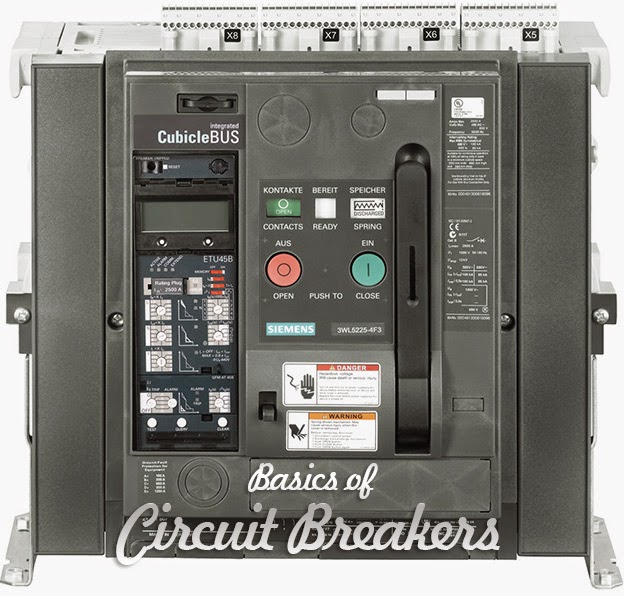
Basics of Circuit Breakers

Basics of Circuit Breakers - SIEMENS

Need for Circuit Protection / Current and Temperature

Current flow in a conductor always generates heat. The greater the current flow, the hotter the conductor. Excess heat is damaging to electrical components and conductor insulation. For that reason, conductors have a rated continuous current carrying capacity or ampacity.
  • Overcurrent protection devices, such as circuit breakers, are used to protect conductors from excessive current flow.
These protective devices are designed to keep the flow of current in a circuit at a safe level to prevent the circuit conductors from overheating.
Excessive current is referred to as overcurrent. The National Electrical Code® – NEC®defines overcurrent as any current in excess of the rated current of equipm ent or the ampacity of a conductor. It may result from overload, short circuit, or ground fault (Article 1 00-Definitions).

Overloads

An overload occurs when too many devices are operated on a single circuit, or a piece of electrical equipment is made to work harder than it is designed for.
For example, a motor rated for 1 0 amps may draw 20, 30, or more amps in an overload condition. In the following illustration, a package has become jammed on a conveyor, causing the motor to work harder and draw more current.
  • Because the motor is drawing more current, it heats up. Damage will occur to the motor in a short time if the problem is not corrected or the circuit is shut down by the overcurrent protector.

Conductor Insulation

Motors, of course, are not the only devices that require circuit protection for an overload condition. Every circuit requires some form of protection against overcurrent. Heat is one of the major causes of insulation failure of any electrical component.
High levels of heat can cause the insulation to breakdown and flake off, exposing conductors.

Short Circuits

When two bare conductors touch, either phase to phase or phase to ground, a short circuit occurs. When a short circuit occurs, resistance drops to almost zero. Short circuit current can be thousands of times higher than normal operating current.
Ohm’s Law demonstrates the relationship of current, voltage, and resistance. For example, a 240 volt motor with 24 Ω of resistance would normally draw 1 0 amps of current.

Types of Overcurrent Protective Devices

Circuit protection would be unnecessary if overloads and short circuits could be eliminated. Unfortunately, overloads and short circuits do occur. To protect a circuit against these currents, a protective device must determine when a fault condition develops and automatically disconnect the electrical equipment from the voltage source.
  • An overcurrent protection device must be able to recognize the difference between overcurrents and short circuits and respond in the proper way. Slight overcurrents can be allowed to continue for some period of time, but as the current magnitude increases, the protection device must open faster.
Short circuits must be interrupted instantaneously. Several devices are available to accomplish this.

Click the download Button then Skip the advertisement and then download the file


Basics of Busway

SIEMENS - Basics of busway

Distribution Systems

A distribution system is a system that distributes electrical power throughout a building. Distribution systems are used in every residential, commercial, and industrial building.
Distribution systems used in commercial and industrial locations are complex.
  • distribution system consists of metering devices to measure power consumption, main and branch disconnects, protective devices, switching devices to start and stop power flow, conductors, and transformers.

Power may be distributed through various switchboardstransformers, and panelboards. Good distribution systems don’t just happen. Careful engineering is required so that the distribution system safely and efficiently supplies adequate electric service to both present and possible future loads.

Feeders

A feeder is a set of conductors that originate at a main distribution center and supplies one or more secondary, or one or more branch circuit distribution centers. Three feeders are used in this example. The first feeder is used for various types of power equipment.
The second feeder supplies a group of 480 VAC motors. The third feeder is used for 120 volt lighting and receptacles.

Bus Bars

Commercial and industrial distribution systems use several methods to transport electrical energy. These methods may include heavy conductors run in trays or conduit. Once installed, cable and conduit assemblies are difficult to change. Power may also be distributed using bus bars in an enclosure. This is referred to as busway.
A bus bar is a conductor that serves as a common connection for two or more circuits. It is represented schematically by a straight line with a number of connections made to it. Standard bus bars in Siemens busway are made of aluminum or copper.

NEMA Definition

Busway is defined by the National Electrical Manufacturers Association (NEMA) as aprefabricated electrical distribution system consisting of bus bars in a protective enclosure, including straight lengths, fittings, devices, and accessories.
Busway includes bus bars, an insulating and/or support material, and a housing.

Click the download Button then Skip the advertisement and then download the file

Basics of Sensors

Sensors

One type of feedback frequently needed by industrial-control systems is the position of one or more components of the operation being controlled. Sensors are devices used to provide information on the presence or absence of an object.

Siemens Sensors

Siemens sensors include limit switches, photoelectric, inductive, capacitive, and ultrasonic sensors. These products are packaged in various configurations to meet virtually any requirement found in commercial and industrial applications. Each type of sensor will be discussed in detail.
At the end of the course an application guide is provided to help determine the right sensor for a given application.

Technologies

Limit switches use a mechanical actuator input, requiring the sensor to change its output when an object is physically touching the switch. Sensors, such as photoelectric, inductive, capacitive, and ultrasonic, change their output when an object is present, but not touching the sensor.
In addition to the advantages and disadvantages of each of these sensor types, different sensor technologies are better suited for certain applications. The following table lists the sensor technologies that will be discussed in this course.

Contact Arrangement

Contacts are available in several configurations. They may be normally open (NO), normally closed (NC), or a combination of normally open and normally closed contacts. Circuit symbols are used to indicate an open or closed path of current flow. Contacts are shown as normally open (NO) or normally closed (NC).
The standard method of showing a contact is by indicating the circuit condition it produces when the contact actuating device is in the deenergized or nonoperated state. For the purpose of explanation in this text a contact or device shown in a state opposite of its normal state will be highlighted.
Highlighted symbols used to indicate the opposite state of a contact or device are not legitimate symbols.

Click the download Button then Skip the advertisement and then download the file