My title page contents

Capicitor Application Issues

Capacitors must be built to tolerate voltages and currents in excess of their ratings according to standards. The applicable standard for power capacitors is IEEE Std 18-2002, IEEE Standard for Shunt Power Capacitors.

Heat as one of most common cause of motor failure

This slide speaks about that how motor operation fails due to heat. how heat affect motors?

Thursday, 14 January 2016

7 guide lines to correctly select circuit breaker

7 guide lines to correctly select circuit breaker 


Selection of rated circuit breaker //
The general procedure for the selection of correctly rated circuit breaker follows the following scheme of seven major questions you should answer:

1. What is the task of the branch circuit or feeder?
Will it be used for the protection of connecting leads, protection of installation, group-protection or motor protection? Select the appropriate circuit breaker type, with or without the thermal overload protection. Decide which type of protective characteristic (cable or motor protection).

2. Which rated current / setting range?
Do the setting ranges of the thermal and the magnetic release cover the requirements of the particular application (protection of transformer or generator)?
The setting ranges of the various sizes of circuit breakers are overlapping. The same current settings may be partly covered by more than one size of circuit breakers (as for example 80 A setting can be covered by two or more CB sizes, 100A or 125A).

The following features depend on the size of the circuit breakers:
Accessories (as for example types and numbers of auxiliary contacts),Mode of operation (toggle or rotating handle),Mode of mounting (snap-on or screw mounting) orThe electrical characteristics (breaking capacity, selectivity etc.).

3. Breaking / making capacities / rated operational voltage?
Where is the point of installation of the circuit breaker?What is the expected agnitude of the prospective short-circuit current at that location?Is a lower making/breaking capacity acceptable (appreciable reduction of the short-circuit current due to long connecting leads or due to other short circuit protective devices connected upstream)?Is the breaking capacity reduced due to higher rated operational voltage (as for example >400 V)?Does it indicate a selection on the basis of Icu (rated ultimate short-circuit breaking capacity, reduced functional capability after the interruption of a short-circuit) or on the basis of Ics (rated service short-circuit breaking capacity, full functional capability after the interruption of the short-circuit)?With the help of an efficient group-protection, can smaller and less expensive circuit breakers be utilised?
Not sure what are the breaking and making capacity?

4. Any special requirements?
Must reduction factors for the rated current be taken into account due to: ambient air temperature (>40…60 °), altitude of the site of installation (>2000 m above m.s.l), higher supply frequency (>400 Hz)?

5. Which type of co-ordination?
Selection of the downstream contactor in accordance with the type of co-ordination type “1” or type “2”?

6. What is the mode of mounting?
Deciding factor for the supporting/adapter plates of the modular mounting system (suitability for the selected type of circuit breaker).

7. Cross-section of the connecting wire/cable?
The cross-section of the connecting leads to the motors are to be selected on the basis of the current setting of the thermal overload release of the circuit breaker. Eventually, the maximum permissible length of the connection is to be considered (shock hazard due to touch potential in the case of a short-circuit).


Capacitive Voltage Transformers for HV Measurements


66 kV and upwards //

Capacitive voltage transformers (CVTs) are used on higher voltage levels, starting from 66 kV and upwards. The type of the CVT is always a single-pole one, thus the connection is between phase and earth. The higher the voltage level is, the more price-competitive the capacitive type becomes.
One of the advantages the capacitive type has, in comparison to the inductive type, is the possibility to use capacitive voltage transformers as high-frequency coupling unitstowards the primary system (over headlines).
A typical application would be to utilize the CVTs for power Line Carrier (PLC)high-frequency signal interface units. For the voltage measurement purposes, the behavior and the data specification of CVTs follow the same guide lines as the inductive ones.
In addition, the possibility for high-frequency signal coupling calls for a specified value for rated capacitance (Cn).
This value is chosen considering the following issues //
  • Voltage magnitude to be measured
  • Demands from PLC system (frequency, bandwidth, connections)
  • Capacitive voltage transformer manufacturing considerations

The construction of capacitive voltage transformers

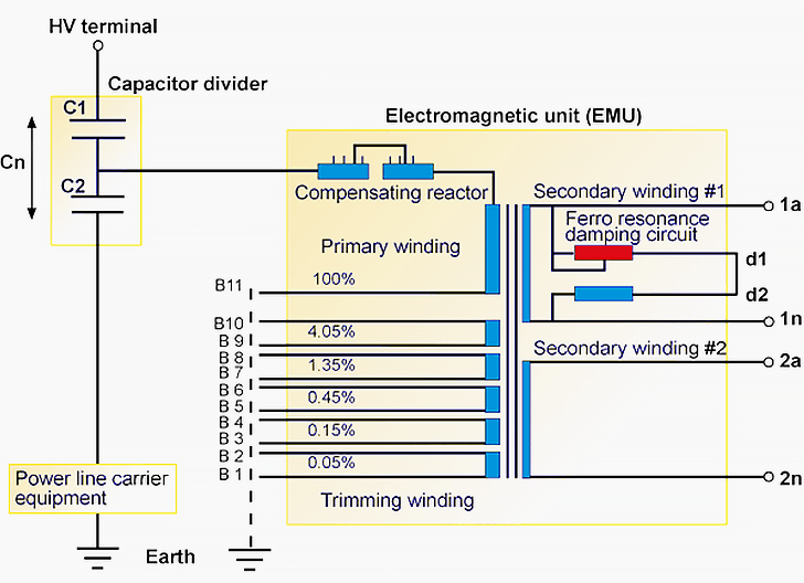
The figure above shows the principle of a capacitive voltage divider on which the capacitive voltage transformer is based. The trimming windings are used for fine tuning the output signal to correspond with the required accuracy class requirements. The compensating reactor compensates the phase angle shift caused by the capacitive voltage divider.


Capacitive voltage transformer’s principal construction
Figure 1 – Capacitive voltage transformer’s principal construction
All capacitive voltage transformers require some sort of ferroresonance damping circuit.
The capacitance in the voltage divider, in series with the inductance of the compensating reactor and the wound transformer (inside the electromagnetic unit EMU), constitutes a tuned resonance circuit. Unlike with the inductive type of voltage transformers the CVTs usually have the ferroresonance damping circuit inbuilt in the CVT itself, as shown in the previous figure.


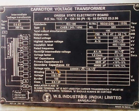
Capacitor voltage transformer (CVT) nameplate
Capacitor voltage transformer (CVT) nameplate (photo credit: technosources.blogspot.rs)
At higher system voltages, the resonance phenomenon usually takes place on fundamental or on sub-harmonic frequencies, resulting in voltage transformer heating (finally damages) and non-selective operations of protective relaying possible protective relaying non-selective operations.
The modern CVTs are utilizing the so-called “adaptive” damping circuits.
The circuit consists of a saturable series reactor and a loading resistor. This circuit is connected in parallel to one of the secondary cores. During ferroresonance conditions, high voltages appear, saturating the reactor and turning the damping resistor on to effectively mitigate the parasitic voltage. During normal system conditions, the reactor presents high reactance, effectively “switching off” the damping resistor.
Possible triggering factors for the ferroresonance phenomena could be //
  • Planned primary switchings in the system
  • Circuit breaker trippings caused by primary fault
  • High-speed autoreclosing
 Transformers (CVT) For HV Measurements
66 kV and upwards //

Capacitive voltage transformers (CVTs) are used on higher voltage levels, starting from 66 kV and upwards. The type of the CVT is always a single-pole one, thus the connection is between phase and earth. The higher the voltage level is, the more price-competitive the capacitive type becomes.
One of the advantages the capacitive type has, in comparison to the inductive type, is the possibility to use capacitive voltage transformers as high-frequency coupling unitstowards the primary system (over headlines).


A typical application would be to utilize the CVTs for power line carrier (PLC)high-frequency signal interface units. For the voltage measurement purposes, the behavior and the data specification of CVTs follow the same guide lines as the inductive ones.
In addition, the possibility for high-frequency signal coupling calls for a specified value for rated capacitance (Cn).
This value is chosen considering the following issues //
Voltage magnitude to be measuredDemands from PLC system (frequency, bandwidth, connections)Capacitive voltage transformer manufacturing considerations
The construction of capacitive voltage transformers
The figure above shows the principle of a capacitive voltage divider on which the capacitive voltage transformer is based. The trimming windings are used for fine tuning the output signal to correspond with the required accuracy class requirements. The compensating reactor compensates the phase angle shift caused by the capacitive voltage divider.
All capacitive voltage transformers require some sort of ferroresonance damping circuit.
The capacitance in the voltage divider, in series with the inductance of the compensating reactor and the wound transformer (inside the electromagnetic unit EMU), constitutes a tuned resonance circuit. Unlike with the inductive type of voltage transformers the CVTs usually have the ferroresonance damping circuit inbuilt in the CVT itself, as shown in the previous figure.
At higher system voltages, the resonance phenomenon usually takes place on fundamental or on sub-harmonic frequencies, resulting in voltage transformer heating (finally damages) and non-selective operations of protective relaying possible protective relaying non-selective operations.
The modern CVTs are utilizing the so-called “adaptive” damping circuits.
The circuit consists of a saturable series reactor and a loading resistor. This circuit is connected in parallel to one of the secondary cores. During ferroresonance conditions, high voltages appear, saturating the reactor and turning the damping resistor on to effectively mitigate the parasitic voltage. During normal system conditions, the reactor presents high reactance, effectively “switching off” the damping resistor.
Possible triggering factors for the ferroresonance phenomena could be //
Planned primary switchings in the systemCircuit breaker trippings caused by primary faultHigh-speed autoreclosing